Vickers double vane pump 2520V21A51CA22R
Instruction Manual for Vickers Double Vane Pump 2520V21A51CA22R
1. Introduction
The Vickers 2520V21A51CA22R is a high-performance double intravane pump designed for industrial hydraulic applications. With over 70 years of Vickers engineering and manufacturing expertise, this pump offers reliable performance, compact structure, and excellent adaptability, making it suitable for a wide range of industrial scenarios requiring stable hydraulic power supply. This manual provides detailed information on the pump’s specifications, features, installation, operation, maintenance, and troubleshooting to ensure safe and efficient use.
2. Product Overview
2.1 Product Description
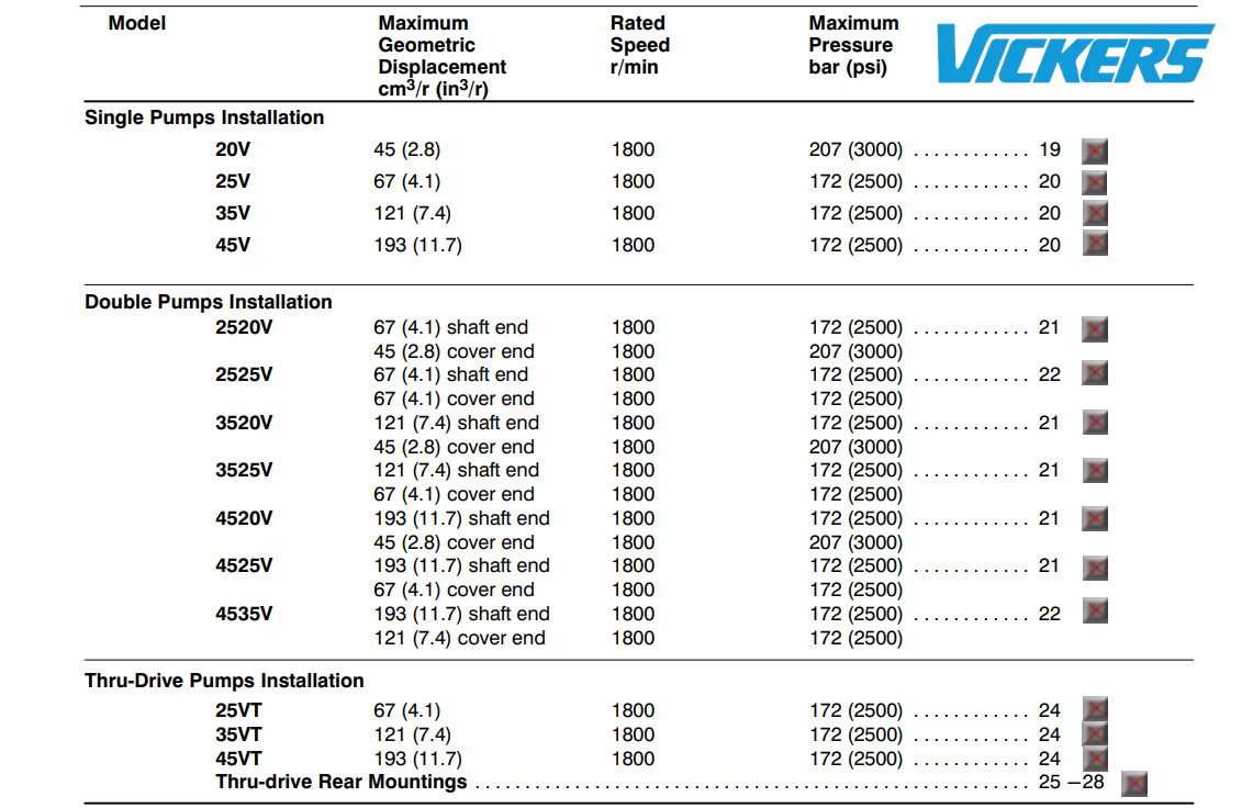
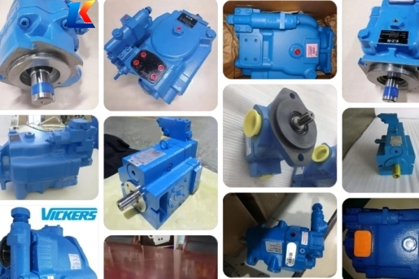
The 2520V21A51CA22R belongs to Vickers V-series double vane pumps, featuring a fixed displacement and balanced intra-vane design. It adopts a double-pump configuration, which can provide two independent oil supply channels, effectively improving the flexibility and efficiency of the hydraulic system. The pump’s vane design with self-wear compensation ensures that the volumetric efficiency remains stable throughout its service life, while the compact size and easy maintenance design maximize the flexibility of equipment layout.
2.2 Key Features
-
High Volumetric Efficiency: Volumetric efficiency exceeds 90%, ensuring effective conversion of mechanical energy to hydraulic energy and reducing energy loss.
-
Low Noise Operation: Sound levels as low as 62 dB(A), meeting the requirements of high-demand industrial environments with strict noise control.
-
High Operating Pressure: Maximum operating pressure up to 207 bar (3000 psi), capable of adapting to high-pressure working conditions.
-
Flexible Installation: Port orientation, pump rotation, and cartridge kit are field changeable, facilitating on-site adjustment and installation.
-
Self-Wear Compensation: The vane automatically adjusts its orbit to maintain contact with the cam ring, ensuring stable performance even with wear between the vane tip and cam ring.
-
Easy Maintenance: The cartridge is independent of the shaft, allowing for easy replacement of flow capacity and on-site maintenance without removing the pump from its mounting.
3. Technical Specifications
|
Specification Item
|
Value
|
|---|---|
|
Model Number
|
2520V21A51CA22R
|
|
Pump Type
|
Double Fixed Displacement Intravane Pump
|
|
Series
|
V-Series
|
|
Maximum Operating Pressure
|
207 bar (3000 psi)
|
|
Maximum Speed
|
1800 rpm
|
|
Displacement (Shaft End)
|
4.1 cu in/revolution (67 cm³/revolution)
|
|
Displacement (Cover End)
|
1.1 cu in/revolution (18 cm³/revolution)
|
|
Flow Rate (Shaft End)
|
21 gal/min @ 1200 rpm; 31.5 gal/min @ 1800 rpm
|
|
Flow Rate (Cover End)
|
5 gal/min @ 1200 rpm; 7.5 gal/min @ 1800 rpm
|
|
Shaft Diameter
|
0.875 in (22.23 mm)
|
|
Shaft Key Size
|
1/4 in
|
|
Shaft Type
|
Straight with Key
|
|
Seal Material
|
Buna-N
|
|
Mounting Flange
|
SAE B, 2 Bolt
|
|
Rotation Direction
|
Right Hand (Clockwise, CW)
|
|
Port Size (Shaft End Pressure Port)
|
1 in Code 61
|
|
Port Size (Cover End Pressure Port)
|
3/4 in Code 61
|
|
Weight
|
45.0 lb (20.41 kg)
|
4. Ordering Code Interpretation
The model number 2520V21A51CA22R follows Vickers standard ordering code rules, with each segment representing specific product parameters:
-
2520V: Series Identifier, indicating 2520V double vane pump
-
21: Displacement Code, corresponding to 67 cm³/revolution (shaft end)
-
A: Port Connection, SAE 4-bolt flange
-
5: Shaft Type, Standard
-
1: Outlet Position, Inline with inlet
-
C: Design Number, 22 (standard design)
-
A: Seal Type, Buna-N (standard seal)
-
22: Design Supplementary Code
-
R: Rotation Direction, Right Hand (Clockwise)
5. Installation Instructions
5.1 Installation Preparation
Before installation, check the pump for damage during transportation, including whether the housing, shaft, and ports are intact. Ensure that the installation site is clean, dry, and free of debris to avoid contamination of the hydraulic system. Prepare the required tools, fasteners, and sealing materials, and confirm that the mounting surface of the equipment is flat and smooth.
5.2 Mounting Steps
-
Align the pump’s mounting flange with the equipment’s mounting surface, ensuring that the shaft is coaxial with the driving motor. The coaxiality error should not exceed 0.1 mm to avoid excessive wear of the shaft and bearing.
-
Use the specified bolts to fasten the pump to the mounting surface, and torque the bolts evenly according to the recommended torque (refer to the equipment manual) to prevent uneven stress on the pump housing.
-
Connect the inlet and outlet pipelines to the pump’s ports. Ensure that the pipeline connection is tight and free of leakage. The inlet pipeline should be as short and straight as possible to reduce suction resistance, and the outlet pipeline should be equipped with a pressure relief valve to protect the pump from overpressure damage.
-
Check the rotation direction of the pump. The pump’s rotation direction is marked on the housing (clockwise for model R). Connect the pump to the driving motor correctly to ensure that the rotation direction is consistent with the mark.
-
Fill the pump and hydraulic system with clean hydraulic oil that meets the specified grade (refer to Section 6.1) before starting the pump.
5.3 Installation Notes
-
Do not install the pump in a location with high temperature, humidity, or corrosive gas to avoid damage to the pump components.
-
Ensure that the inlet pipeline is free of blockage and leakage, and the suction height should not exceed 0.5 meters to prevent cavitation.
-
Do not use excessive force when connecting the pipeline to avoid damaging the pump’s ports.
6. Operation Guidelines
6.1 Hydraulic Oil Requirements
The pump should use high-quality hydraulic oil that meets the following requirements to ensure its normal operation and service life:
-
Viscosity: 10-40 cSt at operating temperature (20-60°C)
-
Cleanliness: ISO 18/15 (NAS 8)
-
Recommended Oil Grade: ISO VG 32 or ISO VG 46 hydraulic oil
-
Do not mix different types or grades of hydraulic oil to avoid chemical reactions that damage the pump components.
6.2 Start-Up Operation
-
Before starting the pump, check the oil level in the hydraulic tank to ensure it is within the specified range.
-
Start the driving motor at low speed (500-800 rpm) and run it for 2-3 minutes to allow the hydraulic oil to circulate and fill the pump. Check for oil leakage at the pipeline connections and pump seals.
-
Gradually increase the motor speed to the rated speed (1800 rpm) and check the pump’s operation status, including noise, vibration, and temperature. The normal operating temperature of the pump should be between 20-60°C. If the temperature exceeds 70°C, stop the pump and check the cause.
-
Check the pressure gauge to ensure that the system pressure is within the maximum operating pressure range of the pump. Do not exceed 207 bar (3000 psi) for a long time.
6.3 Normal Operation
-
During operation, regularly check the pump’s noise, vibration, and temperature. If abnormal noise (such as knocking or squealing) or excessive vibration occurs, stop the pump immediately and troubleshoot.
-
Monitor the system pressure and flow rate to ensure they are stable and meet the working requirements. Avoid long-term operation at maximum pressure to reduce wear of the pump components.
-
Keep the hydraulic oil clean. Regularly check the oil filter and replace it when it is clogged to prevent debris from entering the pump and causing wear.
6.4 Shutdown Operation
-
Gradually reduce the system pressure to zero before shutting down the motor.
-
Stop the driving motor and close the power supply.
-
If the pump will not be used for a long time, drain the hydraulic oil from the pump and hydraulic system, and seal the ports to prevent dust and moisture from entering.
7. Maintenance and Servicing
7.1 Routine Maintenance
Routine maintenance should be performed regularly to ensure the pump’s stable performance. The maintenance cycle can be adjusted according to the operating environment and working hours:
-
Daily Maintenance: Check the oil level, oil temperature, and有无 oil leakage; listen to the pump’s operation noise and check for abnormal vibration.
-
Weekly Maintenance: Clean the surface of the pump and the surrounding area; check the tightness of the bolts and pipeline connections; check the oil filter for clogging.
-
Monthly Maintenance: Take a sample of the hydraulic oil to check its quality. If the oil is contaminated or deteriorated, replace it with new oil; check the seal for wear and replace it if necessary.
-
Annual Maintenance: Disassemble the pump and inspect the internal components (vanes, cam ring, rotor, bearing, etc.) for wear. Replace worn components with original Vickers spare parts; clean the internal cavity of the pump and reassemble it correctly.
7.2 Cartridge Replacement
The pump’s cartridge is independent of the shaft, making it easy to replace without removing the pump from the mounting. Follow these steps:
-
Shut down the pump and relieve the system pressure, then disconnect the power supply and pipeline connections.
-
Remove the bolts that fix the cartridge to the pump housing.
-
Pull out the old cartridge and clean the internal cavity of the pump housing.
-
Install the new cartridge (use original Vickers cartridge) and fasten the bolts evenly.
-
Reconnect the pipelines and power supply, fill the pump with hydraulic oil, and test the pump to ensure it operates normally.
7.3 Spare Parts Requirements
When replacing spare parts, use only original Vickers spare parts to ensure compatibility and performance. Common spare parts include vanes, cam rings, rotors, bearings, seals, and cartridges. The part numbers for spare parts can be obtained from Vickers authorized distributors.
8. Troubleshooting
|
Fault Phenomenon
|
Possible Causes
|
Troubleshooting Methods
|
|---|---|---|
|
No oil output or insufficient flow
|
1. Low oil level in the hydraulic tank; 2. Inlet pipeline blocked or leaking; 3. Vane stuck or worn; 4. Rotation direction incorrect; 5. Suction height too high
|
1. Add hydraulic oil to the specified level; 2. Clean or replace the inlet pipeline, repair leaks; 3. Disassemble the pump, clean or replace the vanes; 4. Correct the rotation direction; 5. Reduce the suction height
|
|
Excessive pump noise
|
1. Cavitation due to insufficient suction; 2. Air entering the hydraulic system; 3. Worn or damaged bearings; 4. Loose bolts or pipeline connections; 5. Hydraulic oil viscosity too high
|
1. Check the inlet pipeline and suction height, eliminate cavitation; 2. Bleed the air from the system; 3. Replace the bearings; 4. Tighten the bolts and pipeline connections; 5. Replace with hydraulic oil of the correct viscosity
|
|
Excessive pump temperature
|
1. Hydraulic oil contamination or deterioration; 2. System pressure too high; 3. Poor heat dissipation of the hydraulic system; 4. Worn internal components causing friction increase
|
1. Replace the hydraulic oil and clean the oil filter; 2. Adjust the system pressure to the normal range; 3. Check the cooling system and improve heat dissipation; 4. Disassemble the pump and replace worn components
|
|
Oil leakage
|
1. Worn or damaged seals; 2. Loose pipeline connections; 3. Cracked pump housing; 4. Excessive system pressure
|
1. Replace the seals; 2. Tighten the pipeline connections; 3. Replace the pump housing; 4. Adjust the system pressure
|
|
Unstable system pressure
|
1. Worn vanes or cam ring; 2. Leakage in the hydraulic system; 3. Pressure relief valve malfunction; 4. Hydraulic oil viscosity unstable
|
1. Replace the vanes or cam ring; 2. Repair the leakage in the system; 3. Inspect and repair the pressure relief valve; 4. Replace with qualified hydraulic oil
|
9. Safety Precautions
-
Before installing, operating, or maintaining the pump, read this manual carefully and follow all instructions to avoid personal injury or equipment damage.
-
Do not operate the pump beyond the maximum operating pressure or speed to prevent pump failure and potential safety hazards.
-
When the pump is running, do not touch the rotating parts (such as the shaft) to avoid personal injury.
-
When performing maintenance or replacing parts, ensure that the system pressure is completely relieved and the power supply is disconnected to avoid accidental start-up.
-
Use appropriate protective equipment (such as gloves, goggles) when handling hydraulic oil or disassembling the pump.
-
Dispose of used hydraulic oil and worn parts in accordance with local environmental protection regulations.
10. Warranty Information
The Vickers 2520V21A51CA22R double vane pump is covered by a standard warranty of 12 months from the date of purchase. The warranty covers manufacturing defects in materials and workmanship. The warranty does not cover damage caused by improper installation, operation, maintenance, or use of non-original spare parts. For warranty service, contact Vickers authorized distributors or the manufacturer with the pump’s model number and purchase date.