Sale


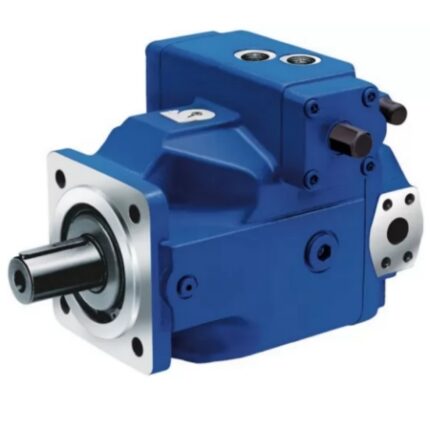
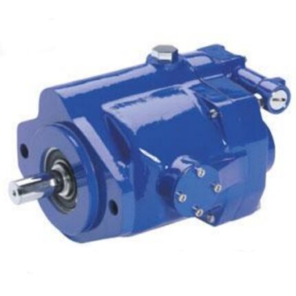
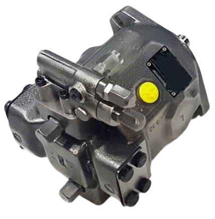
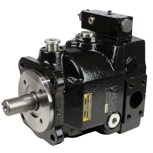
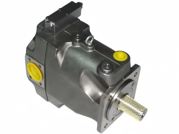
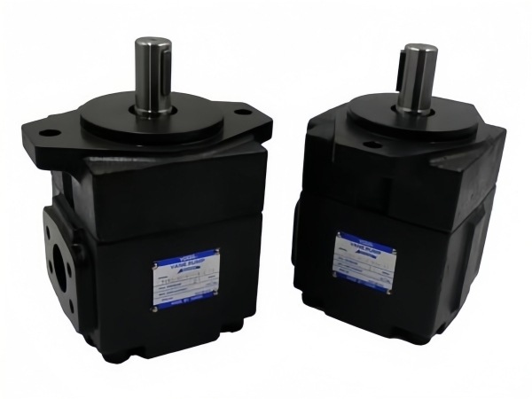
PVH series vickers piston pump
Whats app: +86 13728707767
E-mail: hyd-sales2009@outlook.com
We are a professional manufacturer of hydraulic pumps, offering a complete range of products. Inquiries are welcome! (#^.^#)
Description
1. Product Overview
The Vickers PVH series is a family of high-flow, high-performance variable displacement in-line piston pumps. Integrating proven designs, high-quality manufacturing technology and excellent operational characteristics of other Vickers piston pumps, it features a compact and lightweight structure. Specifically engineered for demanding applications, the series meets the performance requirements of 250 bar (3625 psi) continuous operation for next-generation equipment, and 280 bar (4050 psi) operation in load-sensing systems.
2. Core Specifications
2.1 Displacement Range
-
PVH057: 57.4 cm³/r (3.50 in³/r)
-
PVH063: 63.1 cm³/r (3.85 in³/r)
-
PVH074: 73.7 cm³/r (4.50 in³/r)
-
PVH081: 81.0 cm³/r (4.94 in³/r)
-
PVH098: 98.3 cm³/r (6.00 in³/r)
-
PVH106: Not specified in detail (part of the full series)
-
PVH131: 131.1 cm³/r (8.00 in³/r)
-
PVH141: 141 cm³/r (8.60 in³/r, approximate)
2.2 Pressure Ratings
-
Continuous operating pressure: 250 bar (3625 psi)
-
Operating pressure in load-sensing systems: 280 bar (4050 psi)
-
Standard pressure compensator setting (Type C): 250 bar (3625 psi)
-
Optional pressure compensator setting (Type CM): 70 bar (1015 psi)
-
Maximum inlet pressure (without housing-to-inlet overflow valve): 3.4 bar (50 psi)
2.3 Speed Range
-
Speed range: 500 – 3000 rpm
-
Rated speed: 1500 – 2400 rpm
2.4 Efficiency
Volumetric efficiency: ≥ 95%, ensuring more flow and input energy is used for work rather than converted into heat loss.
2.5 Noise Level
Low-noise design (QI type for industrial applications) is available, suitable for noise-sensitive industrial environments.
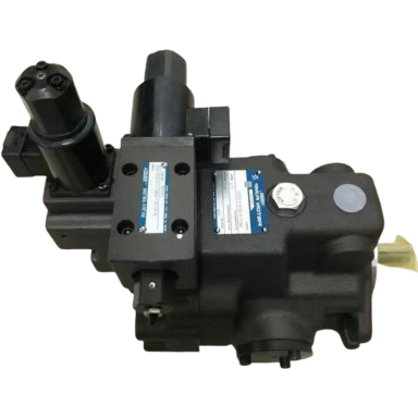
3. Model Coding System
The model coding of PVH series pumps consists of 16 segments, indicating series, displacement, design type, mounting flange, shaft rotation direction, configuration, and other parameters. Key coding details are as follows:
-
Pump Series: PVH
-
Maximum Geometric Displacement: 057/063/074/081/098/131/141 (corresponding to displacement values)
-
Design/Application Type: Blank = For mobile applications; QI = Low-noise design for industrial applications
-
Mounting Flange (Driver End): C = SAE “C” 4-bolt type (SAE J744-127-4); M = ISO 3019/2–125B4HW (only for PVH57 and PVH74)
-
Shaft Rotation Direction (Viewed from Driver End): R = Clockwise; L = Counterclockwise
-
Configuration: Blank = Non-thru-drive (single pump); A = Thru-drive pump with SAE “A” 2-bolt rear flange; B = Thru-drive pump with SAE “A” 2-bolt and 4-bolt rear flange; C = Thru-drive pump with SAE “C” 2-bolt and 4-bolt rear flange
-
Pump Design Number: 10 (design numbers 10-19 have unchanged mounting connection dimensions)
-
Pressure Compensator: C = 70-250 bar (1015-3625 psi) (standard); CM = 40-130 bar (580-1885 psi) (optional QI type); IC = Industrial control with 290 psi differential pressure
-
Factory Setting of Pressure Compensator: 25 = 250 bar (3625 psi) for Type C; 7 = 70 bar (1015 psi) for Type CM (in 10 bar increments)
-
Additional Control Functions: Blank = No additional control; V = Load sensing (290 psi differential pressure); T = Torque limiter; VT = Load sensing + torque limiter
-
Factory Setting of Torque Limiter: Expressed in 10 bar increments (e.g., 8 = 80 bar / 1160 psi; 18 = 180 bar / 2610 psi)
-
Control Design Number: 31 = For C, CM, C**V, or IC control; 13 = For C**T control; 14 = For C**VT control
-
Special Feature Suffix: 027 = Combined 2-bolt/4-bolt mounting (SAE “C”, except PVH131); 031 = Thru-drive SAE “A” seat cover; 041 = Without housing-to-inlet overflow valve; 057 = Shaft upward operation (vertical mounting); S = Adjustable maximum displacement stop (only for non-thru-drive and non-torque control types)
4. Key Features & Advantages
-
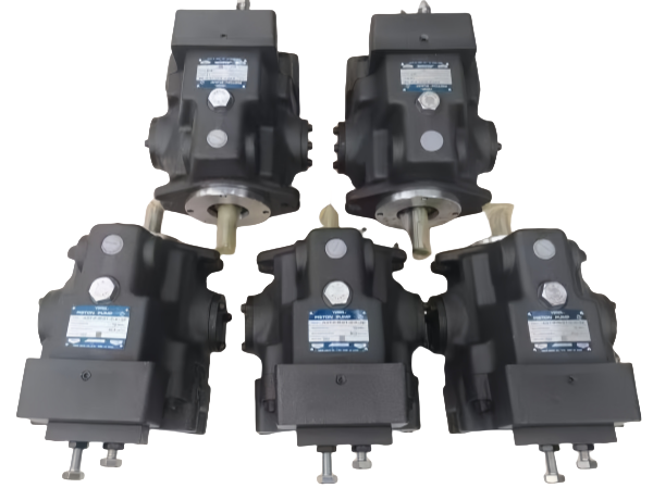
Versatile Design: Available in single pump, thru-drive arrangements, various drive shafts and control options, adapting to any application with cost-effective installation.
-
Heavy-Duty Durability: Proven components in a compact housing ensure long service life at high performance levels; heavy-duty bearings and shafts minimize internal deformation and wear.
-
Easy Maintenance: Compact and lightweight structure facilitates installation and servicing; dedicated service kits for critical rotating and control components simplify maintenance.
-
High Efficiency: Optimized compensators provide effective system control; over 95% volumetric efficiency reduces energy waste.
-
Low Noise: Optional low-noise design for noise-sensitive industrial applications, improving working environment acceptability.
5. Application Scope
Suitable for energy-conscious applications in earthmoving machinery, construction equipment, machine tools, plastic machinery, and other industrial fields requiring high productivity and controllability.
6. Fluid & Installation Requirements
-
Fluid Type: Hydraulic oil (specific grades refer to official guidelines)
-
Oil Cleanliness: Strict adherence to hydraulic system oil cleanliness standards is required (details in application data)
-
Mounting Options: Basic pump (non-thru-drive), thru-drive pump, vertical mounting (shaft upward), with optional mounting bracket kits
Note: Performance curves, detailed installation dimensions, and torque calculation formulas are available in the official technical manual. For customized settings and further technical support, contact Eaton-Vickers authorized distributors.

About brand
Shipping & Delivery