Rexroth hydraulic pump A15VSO series manual
Rexroth Hydraulic Pump A15VSO Series Instruction Manual
1. About This Documentation
1.1 Validity of the Documentation
This instruction manual applies to the Rexroth A15VSO series axial piston variable pump (Series 11). It is valid for all models within the series, including variants with different displacements and control devices. For specific technical data and configuration details, refer to the data sheet 92801 and your order confirmation.
1.2 Required and Supplementary Documentation
In addition to this instruction manual, the following documents are required for safe and correct operation, installation, and maintenance of the pump:
-
Data sheet 92801 (technical data and operating limits)
-
Order confirmation (specific configuration of your pump)
-
Safety regulations for hydraulic systems in your region or industry
-
Instruction manuals for associated components (e.g., couplings, gearboxes, control valves)
1.3 Representation of Information
1.3.1 Safety Instructions
Safety instructions are marked with symbols to indicate the level of risk. Follow all safety instructions to prevent personal injury or property damage.
1.3.2 Symbols
The following symbols are used throughout this manual to highlight important information:
-
⚠️ Warning: Indicates a potential hazard that could result in serious personal injury or death if not avoided.
-
⚠️ Caution: Indicates a potential hazard that could result in minor personal injury or property damage if not avoided.
-
ℹ️ Note: Provides additional information to ensure correct operation and extend the service life of the pump.
1.3.3 Designations
All designations (model numbers, component names, part numbers) used in this manual correspond to the official Rexroth product designations. For replacement parts, always use the exact designation provided in the spare parts section.
1.3.4 Abbreviations
Common abbreviations used in this manual:
-
bar: Bar (pressure unit)
-
cc/rev: Cubic centimeters per revolution (displacement unit)
-
rpm: Revolutions per minute (speed unit)
-
ISO: International Organization for Standardization
-
VG: Geometric displacement
2. Safety Instructions
2.1 About This Chapter
This chapter contains essential safety instructions for the installation, operation, maintenance, and repair of the A15VSO series pump. Failure to comply with these instructions may result in personal injury, property damage, or damage to the pump itself.
2.2 Intended Use
The A15VSO series is an axial piston variable pump with a swashplate design, intended for use in open-circuit hydrostatic drives in industrial applications (e.g., machine tools, metallurgical equipment, construction machinery). It is designed to generate, control, and regulate hydraulic fluid flow. The pump may be used either self-priming or with a charge pump.
Any use beyond the intended scope or modification of the pump without prior approval from Rexroth is considered improper use and may void the warranty.
2.3 Improper Use
The following uses are considered improper and are strictly prohibited:
-
Use in closed-circuit hydraulic systems without appropriate modifications.
-
Operation beyond the specified pressure, speed, or temperature limits.
-
Use with hydraulic fluids that do not meet the specified requirements.
-
Use in explosive or highly corrosive environments without special protection.
-
Modification of the pump’s control devices or structural components.
2.4 Personnel Qualifications
All work related to the pump (installation, commissioning, operation, maintenance, repair) must be performed by qualified personnel who have received appropriate training in hydraulic systems and are familiar with the contents of this manual. Qualified personnel must understand the hazards associated with hydraulic systems (e.g., high pressure, moving parts) and know how to take appropriate safety measures.
2.5 General Safety Instructions
-
Always wear appropriate personal protective equipment (PPE) when working with the pump, including safety glasses, gloves, and safety shoes.
-
Before performing any work on the pump, shut down the drive motor, relieve all hydraulic pressure, and lock out the power supply to prevent accidental start-up.
-
Inspect the pump and associated components regularly for leaks, damage, or wear. Repair or replace damaged parts immediately.
-
Keep the work area clean and free of obstacles to avoid tripping or falling hazards.
-
Do not open or disassemble the pump while it is under pressure or in operation.
-
Store hydraulic fluids in a cool, dry place, away from heat sources and open flames.
2.6 Product-Specific Safety Instructions
-
⚠️ Warning: The pump operates at high pressure (up to 420 bar). Leaks in the hydraulic system can cause severe personal injury. Check all connections regularly for leaks and tighten loose fittings.
-
⚠️ Warning: Moving parts (e.g., drive shaft, coupling) can cause entanglement or crushing injuries. Install appropriate guards before operating the pump.
-
⚠️ Caution: Do not exceed the maximum swashplate angle, as this can cause excessive wear and damage to the pump.
-
⚠️ Caution: Ensure the hydraulic fluid is clean and meets the specified viscosity requirements. Contaminated or incorrect fluid can damage the pump’s internal components.
2.7 Personal Protective Equipment
The following PPE is required when working with the A15VSO series pump:
-
Safety glasses: To protect against hydraulic fluid splashes and flying debris.
-
Chemical-resistant gloves: To protect against hydraulic fluid and other chemicals.
-
Safety shoes: To protect against falling objects and slips.
-
Hearing protection: If the pump operates at high noise levels (exceeding 85 dB(A)).
3. General Instructions on Property Damage and Product Damage
To prevent damage to the pump and associated equipment, follow these instructions:
-
Do not subject the pump to excessive vibration or shock during transport or installation.
-
Ensure the pump is installed on a stable, level surface that can support its weight.
-
Avoid operating the pump with insufficient hydraulic fluid, as this can cause cavitation and damage to internal components.
-
Do not allow the hydraulic fluid temperature to exceed 80°C, as this can reduce the fluid’s viscosity and damage seals and bearings.
-
Use only genuine Rexroth spare parts. Non-genuine parts may not meet the required specifications and can cause damage to the pump.
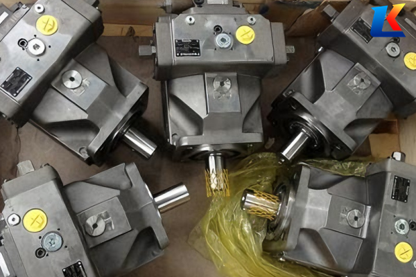
4. Scope of Delivery
The standard scope of delivery for the A15VSO series pump includes:
-
A15VSO axial piston variable pump (as per order confirmation)
-
Instruction manual (this document)
-
Mounting hardware (bolts, washers)
-
Sealing elements (if required)
-
Product identification label
Check the delivery against the order confirmation upon receipt. Report any missing or damaged items to Rexroth or your authorized distributor immediately.
5. About This Product
5.1 Performance Description
The A15VSO series is a variable displacement axial piston pump designed for stationary industrial applications. It generates hydraulic fluid flow that is proportional to the drive speed and geometric displacement. The flow rate can be infinitely adjusted by changing the swashplate angle, allowing for precise control of the hydraulic system.
5.2 Product Description
The A15VSO pump features a swashplate design with an axial piston rotary group, suitable for open-circuit hydrostatic drives. In an open circuit, hydraulic fluid flows from the reservoir to the pump, is delivered to the consumer (e.g., hydraulic motor), and then returns directly to the reservoir. The pump is available in displacement sizes 110, 145, 175, 210, and 280 cc/rev, with a nominal pressure of 350 bar and a maximum pressure of 420 bar.
5.2.1 Axial Piston Unit Layout
The axial piston unit consists of the following key components (see Figure 2 in the original manual):
-
Drive shaft (1): Transmits power to the piston group.
-
Retaining plate (2): Secures the swashplate and other components.
-
High-pressure side (3): Delivers pressurized hydraulic fluid to the system.
-
Charge pump (impeller) (4): Optional component for priming the main pump.
-
Version without through drive (5): For standalone operation.
-
Version with through drive (6): Allows for mounting additional gear or axial piston pumps (100% through drive).
-
Control plate (distributor plate) (7): Directs hydraulic fluid to and from the pistons.
-
Suction side (8): Draws hydraulic fluid from the reservoir.
-
Cylinder (9): Houses the pistons.
-
Piston (10): Converts rotational motion into linear motion to generate pressure.
-
Slipper pad (11): Reduces friction between the pistons and swashplate.
-
Swashplate (cradle) (12): Adjusts the piston stroke to vary the flow rate.
5.2.2 Functional Description
When the drive shaft rotates, the pistons move back and forth within the cylinders due to the inclined angle of the swashplate. As the pistons retract, hydraulic fluid is drawn into the cylinder through the suction side. As the pistons extend, the fluid is pressurized and discharged through the high-pressure side. Adjusting the swashplate angle changes the piston stroke, thereby varying the flow rate. A larger swashplate angle results in a larger stroke and higher flow rate, while a smaller angle results in a smaller stroke and lower flow rate.
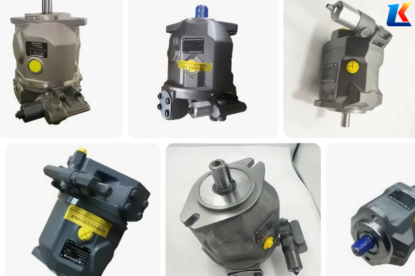
5.3 Product Identification
Each A15VSO pump is equipped with a product identification label located on the pump housing. The label contains the following information:
-
Model number (e.g., A15VSO 180 DRG7155-110)
-
Serial number
-
Nominal displacement
-
Nominal pressure
-
Manufacturing date
-
Bosch Rexroth AG logo
Record the serial number and model number in the space provided below for future reference:
Model Number: _________________________
Serial Number: _________________________
6. Transport and Storage
6.1 Transporting the Axial Piston Unit
Proper transport is essential to prevent damage to the pump. Follow these instructions when transporting the pump:
6.1.1 Transport by Hand
Only transport small-sized pumps (displacement ≤ 110 cc/rev) by hand. Use the designated lifting points on the pump housing and ensure a firm grip. Do not lift the pump by the drive shaft, control devices, or hydraulic connections, as this can damage these components.
6.1.2 Transport with Lifting Devices
For larger pumps (displacement > 110 cc/rev), use a crane, hoist, or other appropriate lifting device. Use lifting slings that are rated for the pump’s weight (refer to the product data sheet for the exact weight). Attach the slings to the designated lifting points and ensure the pump is balanced to prevent tilting. Do not allow the pump to swing freely during transport, as this can cause collisions and damage.
⚠️ Warning: Ensure the lifting device is in good working condition and rated for the load. Always have a qualified operator operate the lifting device.
6.2 Storing the Axial Piston Unit
Store the pump in a clean, dry, and well-ventilated area. Follow these storage instructions:
-
Store the pump in its original packaging until installation to protect it from dust, moisture, and damage.
-
Store the pump in a horizontal position to prevent oil leakage and damage to internal components.
-
Maintain a storage temperature between -20°C and +40°C. Avoid extreme temperature fluctuations.
-
Keep the pump away from heat sources, open flames, and corrosive substances.
-
If the pump is stored for more than 6 months, rotate the drive shaft by hand 1-2 full turns every month to prevent seizure of internal components.
-
Ensure the hydraulic ports are sealed with the provided plugs to prevent contamination.
7. Installation
7.1 Unpacking
Unpack the pump carefully to avoid damage. Remove the packaging material and inspect the pump for any visible damage (e.g., dents, scratches, broken components). Check that all parts are present and in good condition. If any damage is found, contact Rexroth or your authorized distributor immediately.
7.2 Installation Conditions
The pump must be installed in a location that meets the following conditions:
-
Stable, level surface with sufficient load-bearing capacity.
-
Adequate space around the pump for maintenance and operation (minimum 300 mm clearance on all sides).
-
远离 excessive heat, moisture, dust, and corrosive environments.
-
Free from excessive vibration (vibration amplitude ≤ 0.1 mm at 1500 rpm).
-
Access to the pump’s control devices and hydraulic connections for adjustment and maintenance.
7.3 Installation Position
The A15VSO pump can be installed in three different positions, depending on the system configuration:
7.3.1 Below-Reservoir Installation (Standard)
This is the standard installation position, where the pump is mounted below the hydraulic reservoir. The suction port is connected to the reservoir via a suction line. This position ensures optimal suction conditions and prevents cavitation. Ensure the suction line is as short and straight as possible, with a diameter equal to or larger than the pump’s suction port.
7.3.2 Inside-Reservoir Installation
In this position, the pump is mounted inside the hydraulic reservoir. This saves space and reduces noise. Ensure the pump is mounted securely to the reservoir wall and that there is sufficient clearance for the drive shaft and connections. The suction port is directly immersed in the hydraulic fluid, eliminating the need for a separate suction line.
7.3.3 Above-Reservoir Installation
This position is used when space is limited below the reservoir. The pump is mounted above the reservoir, and the suction line is connected to the bottom of the reservoir. To prevent cavitation, ensure the suction line is short and has a large diameter, and the pump is not mounted more than 1 meter above the reservoir’s fluid level. A charge pump may be required for reliable priming.
7.4 Installing the Axial Piston Unit
7.4.1 Preparation
Before installing the pump, perform the following preparation steps:
-
Clean the mounting surface to remove dirt, grease, and debris.
-
Inspect the drive shaft for any damage or bends. Rotate the shaft by hand to ensure it turns smoothly without resistance.
-
Check the hydraulic ports for any contamination and clean them if necessary.
-
Ensure the mounting bolts are the correct size and torque rating (refer to the technical data sheet).
7.4.2 Dimensions
Refer to the technical data sheet (92801) for the exact dimensions of the pump, including mounting hole positions, port sizes, and overall dimensions. Ensure the mounting surface matches the pump’s base dimensions to prevent misalignment.
7.4.3 General Instructions
When installing the pump, follow these general instructions:
-
Mount the pump securely to the mounting surface using the provided bolts. Tighten the bolts to the specified torque (refer to the technical data sheet) in a crisscross pattern to ensure even pressure.
-
Ensure the pump is aligned with the drive motor. The coaxiality error between the pump shaft and motor shaft must be ≤ 0.1 mm to prevent vibration and wear.
-
Use a flexible coupling to connect the pump shaft to the motor shaft. This helps absorb minor misalignments and reduce vibration.
-
Do not use the pump as a support for the motor or other components.
7.4.4 Installation with a Coupling
When using a coupling to connect the pump to the motor:
-
Select a coupling that is rated for the pump’s maximum torque and speed.
-
Align the pump and motor shafts using a dial indicator. Adjust the motor position until the coaxiality error is within the specified limit.
-
Mount the coupling halves on the pump and motor shafts, ensuring they are secured tightly with set screws.
-
Install the coupling guard to prevent access to moving parts.
7.4.5 Installation on a Gearbox
If the pump is mounted on a gearbox:
-
Ensure the gearbox output shaft is compatible with the pump’s drive shaft (same diameter, keyway size).
-
Align the pump and gearbox shafts to ensure coaxiality.
-
Use a coupling or direct connection (if specified) to connect the shafts.
-
Secure the pump to the gearbox using the appropriate mounting hardware.
7.4.6 Installation with Cardan Shaft
For installations where the pump and motor are not aligned, a cardan shaft can be used. Follow the cardan shaft manufacturer’s instructions for installation and alignment. Ensure the cardan shaft is rated for the pump’s torque and speed, and that the angles between the shafts are within the specified limits.
7.4.7 Completion of Assembly
After installing the pump, perform the following checks:
-
Rotate the pump drive shaft by hand to ensure it turns smoothly without resistance.
-
Check that all mounting bolts are tight.
-
Ensure the coupling guard is installed correctly.
-
Verify that there is sufficient clearance around the pump for maintenance and operation.
7.4.8 Hydraulically Connecting the Axial Piston Unit
Follow these instructions to connect the pump to the hydraulic system:
-
Use hydraulic hoses and fittings that are rated for the pump’s maximum pressure (420 bar). Ensure the hoses are compatible with the hydraulic fluid used.
-
Clean all hydraulic connections before assembly to prevent contamination.
-
Connect the suction line to the pump’s suction port. Ensure the line is tight and free from leaks. If using a below-reservoir installation, the suction line should slope slightly downward from the pump to the reservoir to prevent air pockets.
-
Connect the high-pressure line to the pump’s high-pressure port. Use a pressure relief valve in the high-pressure line to protect the pump and system from overpressure.
-
Connect the drain line to the pump’s drain port. The drain line should be as short as possible and have a diameter equal to or larger than the drain port. The drain line should not be restricted, as this can cause pressure buildup in the pump’s housing.
-
Install a filter in the suction line (recommended filtration level: 10 μm) to prevent contamination from entering the pump.
7.4.9 Electrically Connecting the Axial Piston Unit
If the pump is equipped with electrical control devices (e.g., solenoid valves, position sensors), follow these instructions for electrical connection:
-
Ensure the power supply voltage matches the control device’s specifications (refer to the product data sheet).
-
Turn off the power supply before making any electrical connections.
-
Connect the electrical wires to the control device’s terminals according to the wiring diagram provided in the technical data sheet.
-
Secure the wires with cable ties to prevent damage from moving parts.
-
Check the electrical connections for tightness and insulation to prevent short circuits.
7.5 Performing Flushing Cycle
Before commissioning the pump, perform a flushing cycle to remove any contamination from the hydraulic system. Follow these steps:
-
Fill the hydraulic reservoir with the recommended hydraulic fluid (refer to Section 15.2).
-
Disconnect the high-pressure line from the pump and connect it to a temporary flushing line that returns the fluid to the reservoir.
-
Start the drive motor and run the pump at a low speed (500-1000 rpm) for 30-60 minutes.
-
Check the fluid for contamination (e.g., dirt, metal particles). If the fluid is contaminated, replace it and repeat the flushing cycle.
-
After flushing, reconnect the high-pressure line and check for leaks.
8. Commissioning
8.1 Initial Commissioning
After installation and flushing, perform the initial commissioning to ensure the pump operates correctly. Follow these steps:
8.1.1 Filling the Axial Piston Unit
Before starting the pump, ensure the hydraulic system is filled with the correct hydraulic fluid. Open the air vents on the pump and system components to release any trapped air. Continue filling until fluid flows out of the air vents, then close the vents. Check the fluid level in the reservoir and top up if necessary (the fluid level should be between the minimum and maximum marks on the reservoir).
8.1.2 Testing the Hydraulic Fluid Supply
Start the drive motor and run the pump at a low speed (500-1000 rpm). Check the suction line for leaks and ensure the pump is drawing fluid from the reservoir. Listen for any unusual noises (e.g., cavitation, grinding), which may indicate insufficient fluid supply or air in the system. If unusual noises are heard, stop the pump immediately and investigate the cause.
8.1.3 Performing a Functional Test
Increase the pump speed to the recommended operating speed (refer to Section 15.1). Check the following:
-
Hydraulic pressure: Ensure the pressure is within the specified range (nominal pressure 350 bar).
-
Flow rate: Verify that the flow rate is proportional to the swashplate angle.
-
Control devices: Test the control devices (e.g., swashplate adjustment, pressure relief valve) to ensure they operate correctly.
-
Leaks: Check all hydraulic connections and the pump housing for leaks. Tighten any loose fittings if necessary.
-
Temperature: Monitor the hydraulic fluid temperature. It should not exceed 80°C during initial commissioning.
8.2 Running-In Phase
After the functional test, run the pump at the recommended operating speed and pressure for a running-in phase of 50-100 hours. During this phase, check the fluid condition regularly and replace the hydraulic filter after the first 50 hours. This helps to remove any metal particles or debris generated during the initial operation.
8.3 Recommissioning After Standstill
If the pump has been out of operation for more than 6 months, follow these steps before recommissioning:
-
Inspect the hydraulic fluid for contamination and replace it if necessary.
-
Rotate the pump drive shaft by hand 1-2 full turns to ensure it turns smoothly.
-
Check all hydraulic connections and electrical connections for tightness.
-
Perform the flushing cycle (Section 7.5) to remove any contamination.
-
Follow the initial commissioning steps (Section 8.1) to ensure the pump operates correctly.
9. Operation
The A15VSO pump is designed for continuous operation under normal operating conditions. Follow these instructions for safe and efficient operation:
-
Operate the pump within the specified pressure, speed, and temperature limits (refer to Section 15).
-
Monitor the hydraulic fluid level and temperature regularly. Top up the fluid as needed and ensure the temperature does not exceed 80°C.
-
Check the pump for unusual noises, vibrations, or leaks during operation. If any issues are detected, stop the pump immediately and investigate the cause.
-
Do not adjust the swashplate angle or control devices while the pump is under full load, as this can cause sudden pressure or flow changes.
-
If the pump is equipped with a charge pump, ensure it is operating correctly to maintain adequate suction pressure.
-
Avoid operating the pump with a empty or nearly empty reservoir, as this can cause cavitation and damage to internal components.
10. Maintenance and Repair
10.1 Cleaning and Care
Regular cleaning and care are essential to extend the service life of the pump. Follow these instructions:
-
Keep the pump housing clean and free from dirt, grease, and debris. Use a clean cloth to wipe down the pump regularly.
-
Clean the hydraulic reservoir and filter regularly to prevent contamination. Replace the filter element according to the maintenance schedule (Section 10.3).
-
Inspect the hydraulic hoses for cracks, wear, or damage. Replace any damaged hoses immediately.
-
Keep the pump’s cooling system (if equipped) clean and free from obstructions to ensure proper heat dissipation.
10.2 Inspection
Perform regular inspections to detect potential issues early. The following inspections should be performed at the specified intervals:
-
Daily inspection: Check fluid level, temperature, and for leaks. Listen for unusual noises.
-
Weekly inspection: Check the condition of the coupling, mounting bolts, and electrical connections. Inspect the suction and high-pressure lines for damage.
-
Monthly inspection: Check the swashplate angle adjustment mechanism for smooth operation. Inspect the pump housing for signs of wear or damage.
-
Annual inspection: Disassemble the pump (or have it disassembled by a qualified technician) to inspect internal components (e.g., pistons, slipper pads, swashplate) for wear. Replace any worn components as needed.
10.3 Maintenance
Follow this maintenance schedule to ensure the pump operates reliably:
-
After 50 hours of operation: Replace the hydraulic filter element.
-
After 2000 hours of operation: Replace the hydraulic fluid and filter element. Inspect the suction and high-pressure valves for wear.
-
After 4000 hours of operation: Inspect the swashplate, pistons, and slipper pads for wear. Replace any worn components. Check the bearing clearance and replace the bearings if necessary.
-
Every 6 months: Check the tightness of all mounting bolts and hydraulic connections. Tighten any loose fittings.
Note: The maintenance intervals may be shortened if the pump is operated in harsh conditions (e.g., high temperature, high contamination, heavy load).
10.4 Repair
Repair work should only be performed by qualified technicians who are familiar with the A15VSO series pump. Follow these instructions for repair:
-
Before performing any repair work, shut down the drive motor, relieve all hydraulic pressure, and lock out the power supply.
-
Disassemble the pump in a clean, dust-free environment to prevent contamination of internal components.
-
Use only genuine Rexroth spare parts. Non-genuine parts may not meet the required specifications and can cause damage to the pump.
-
Follow the disassembly and assembly instructions provided in the technical data sheet.
-
After repair, perform the flushing cycle (Section 7.5) and initial commissioning (Section 8.1) to ensure the pump operates correctly.
10.5 Spare Parts
Genuine Rexroth spare parts are available from Rexroth or your authorized distributor. When ordering spare parts, provide the pump’s model number and serial number to ensure you receive the correct parts. The following are common spare parts for the A15VSO series pump:
-
Piston and slipper pad assembly
-
Swashplate
-
Control plate (distributor plate)
-
Sealing elements (O-rings, gaskets)
-
Bearings
-
Filter elements
11. Removal and Replacement
11.1 Required Tools
The following tools are required for removing and replacing the pump:
-
Socket wrench set
-
Torque wrench
-
Screwdrivers (flathead and Phillips)
-
Puller (for removing the coupling)
-
Lifting device (crane or hoist)
-
Clean cloths and cleaning solvent
11.2 Preparing for Removal
Before removing the pump, perform the following steps:
-
Shut down the drive motor and lock out the power supply to prevent accidental start-up.
-
Relieve all hydraulic pressure by opening the pressure relief valve or bleeding the system.
-
Disconnect the hydraulic hoses (suction, high-pressure, drain) from the pump. Cap the hoses and pump ports to prevent contamination.
-
Disconnect the electrical connections (if applicable) from the pump’s control devices.
-
Remove the coupling guard and disconnect the coupling from the pump shaft.
11.3 Performing the Disassembly
Follow these steps to remove the pump from the mounting surface:
-
Use a lifting device to support the pump’s weight.
-
Loosen and remove the mounting bolts that secure the pump to the mounting surface.
-
Carefully lift the pump off the mounting surface, ensuring it does not collide with other components.
-
Place the pump on a clean, flat surface for inspection or replacement.
11.4 Preparing the Components for Storage or Further Use
If the pump is to be stored or reused, follow these steps:
-
Clean the pump housing and hydraulic ports with a clean cloth and cleaning solvent.
-
Seal the hydraulic ports with the provided plugs to prevent contamination.
-
Apply a thin layer of hydraulic fluid to the pump’s internal components to prevent corrosion.
-
Store the pump in a clean, dry, and well-ventilated area (refer to Section 6.2).
12. Disposal
When the pump reaches the end of its service life, it must be disposed of in accordance with local environmental regulations. Follow these guidelines:
-
Drain all hydraulic fluid from the pump and dispose of it in accordance with local regulations for hazardous waste.
-
Disassemble the pump and separate the components by material (e.g., metal, plastic, rubber).
-
Recycle or dispose of the components in accordance with local environmental laws. Metal components can be recycled, while plastic and rubber components may need to be disposed of as hazardous waste.
-
Do not dispose of the pump in household waste.
13. Extension and Conversion
Any extension or conversion of the pump (e.g., adding a control device, modifying the through drive) must be approved by Rexroth in advance. Unauthorized extensions or conversions may void the warranty and cause damage to the pump or system. Contact Rexroth or your authorized distributor for information on approved extensions and conversions.
14. Troubleshooting
14.1 How to Proceed for Troubleshooting
If the pump is not operating correctly, follow these steps to identify and resolve the issue:
-
Stop the pump and ensure it is safe to work on (power off, pressure relieved).
-
Gather information about the problem (e.g., unusual noise, low pressure, no flow, leaks).
-
Inspect the pump and associated components for obvious issues (e.g., leaks, loose connections, damaged parts).
-
Check the hydraulic fluid level, temperature, and condition.
-
Test the control devices to ensure they are operating correctly.
-
Refer to the malfunction table below for common issues and solutions.
-
If the issue cannot be resolved, contact Rexroth or your authorized distributor for assistance.
14.2 Malfunction Table
|
Malfunction
|
Possible Cause
|
Solution
|
|---|---|---|
|
No flow or low flow
|
1. Insufficient hydraulic fluid level2. Suction line blocked or leaking3. Air in the system4. Swashplate angle set to minimum5. Control device malfunction6. Internal component wear (pistons, control plate)
|
1. Top up hydraulic fluid2. Clean or replace suction line, tighten connections3. Bleed air from the system4. Adjust swashplate angle5. Inspect and repair/replace control device6. Disassemble and replace worn components
|
|
Low pressure
|
1. Pressure relief valve malfunction2. Hydraulic leaks3. Swashplate angle not adjusted correctly4. Internal leakage (worn seals, pistons)5. Control device not functioning
|
1. Inspect and repair/replace pressure relief valve2. Locate and repair leaks3. Adjust swashplate angle4. Disassemble and replace worn components5. Inspect and repair control device
|
|
Unusual noise (cavitation)
|
1. Insufficient suction pressure2. Suction line too small or restricted3. Air in the system4. Hydraulic fluid viscosity too high5. Suction filter blocked
|
1. Check suction line and ensure adequate fluid supply2. Replace suction line with larger diameter3. Bleed air from the system4. Use hydraulic fluid with correct viscosity5. Clean or replace suction filter
|
|
Overheating
|
1. Hydraulic fluid level too low2. Cooling system malfunction3. Operating pressure too high4. Internal friction (worn components)5. Hydraulic fluid contamination
|
1. Top up hydraulic fluid2. Inspect and repair cooling system3. Adjust pressure to specified limits4. Disassemble and replace worn components5. Replace hydraulic fluid and filter
|
|
Leaks
|
1. Loose hydraulic connections2. Damaged seals or gaskets3. Cracked pump housing or lines4. Overpressure
|
1. Tighten connections2. Replace seals or gaskets3. Replace damaged housing or lines4. Adjust pressure to specified limits
|