Rexroth hydraulic pump A4VG series manual
Instruction Manual for Rexroth A4VG Series Axial Piston Variable Pump
1. Product Description
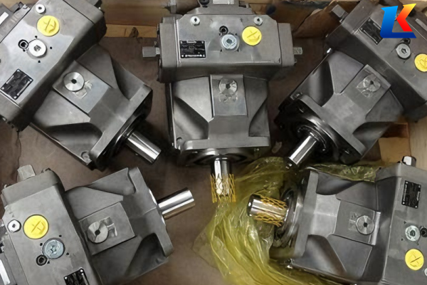
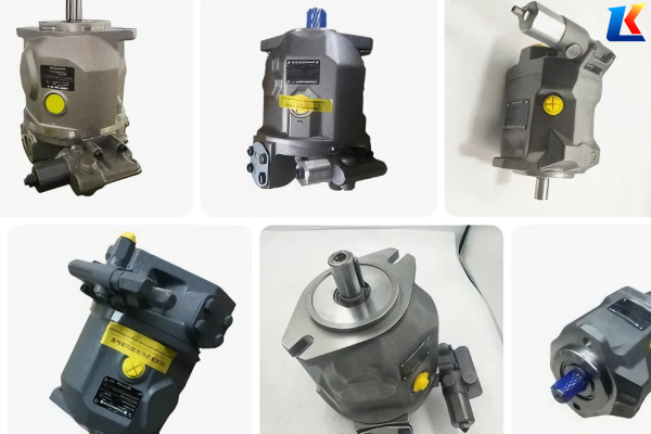
The Rexroth A4VG series is a high-performance axial piston variable pump with a swashplate design, specifically engineered for closed-circuit hydrostatic drives. Distinguished from open-circuit pumps, the A4VG series features bidirectional flow capability, allowing for precise control of hydraulic motors in both forward and reverse directions. It is widely applied in heavy-duty mobile and industrial hydraulic systems, such as construction machinery, mining equipment, and marine propulsion systems, where high efficiency, compact structure, and reliable performance are critical.
Key Features:
-
Closed-circuit design with bidirectional flow, enabling seamless forward/reverse operation of hydraulic motors
-
High nominal and peak pressure ratings, ensuring stable performance under heavy load conditions
-
Optimized swashplate design for low noise emission and reduced energy consumption
-
Integrated charge pump and relief valve, simplifying system configuration and reducing external components
-
Fast and precise control response, adapting to dynamic load changes in real time
-
Robust drive shaft with high axial and radial load capacity, extending service life in harsh environments
-
Modular control options, supporting flexible customization to meet specific application requirements
-
Wide range of displacement sizes, providing versatile solutions for different flow demand scenarios
-
Compatible with various hydraulic fluids, including mineral oil and environmentally friendly HFC fluids (with specific adaptations)
-
Compact and lightweight design, saving installation space in equipment with limited layout room
2. Type Code Explanation
The type code of the A4VG series pump contains key information about its configuration, including displacement, control device, series, and hydraulic fluid version. The following is a detailed explanation of the standard type code structure (specific configurations may vary by model):
|
Position
|
Code
|
Description
|
|
01
|
A4VG
|
Axial piston unit, swashplate design, variable displacement, closed-circuit operation, nominal pressure 400 bar, maximum pressure 450 bar
|
|
02
|
Size (NG)
|
Geometric displacement, including 28, 40, 56, 71, 90, 125, 180, 250, 355 (see technical data for details)
|
|
03
|
Control Device
|
Various options available, e.g., DR (pressure controller), FR (flow controller), MA (manual control), EM (electric proportional control), HD (hydraulic differential control) (see separate data sheets for details)
|
|
04
|
Series
|
Series 25, 32, 40, 50, with specific adaptations for different pressure levels and control functions
|
|
05
|
Charge Pump
|
C for integrated charge pump (standard); no code for without charge pump (special configuration)
|
|
06
|
Hydraulic Fluid Version
|
No code for mineral oil; E for HFA, HFB, HFC hydraulic fluids; W for winterized version (low-temperature adaptation)
|
3. Technical Data
The following technical data are general specifications for the A4VG series. For detailed data of specific models, refer to the order confirmation and technical data sheet RE 92065.
|
Parameter
|
Specification
|
|
Nominal Pressure
|
400 bar
|
|
Maximum Pressure (Peak)
|
450 bar (intermittent operation)
|
|
Size Range (NG)
|
28 to 355
|
|
Operating Viscosity Range
|
10 to 400 mm²/s (at operating temperature); refer to technical data sheet RE 92065 for detailed selection
|
|
Permissible Hydraulic Fluids
|
1. Mineral oil (complying with DIN 51524); 2. HFC hydraulic fluids (water content approx. 35-55 weight percent, complying with ISO 12922); 3. HFD-U fire-resistant fluids (with prior confirmation from Bosch Rexroth)
|
|
Installation Position
|
Any position; vertical installation is recommended for optimal lubrication
|
|
Charge Pump Pressure
|
10-16 bar (adjustable via integrated relief valve)
|
4. Installation Instructions
4.1 Installation Preparation
-
Before installation, inspect the pump for transportation damage. Check the pump body, connectors, and integrated components (charge pump, relief valve) for cracks, dents, or oil leakage.
-
Prepare tools and accessories, including high-pressure mounting bolts, compatible seals (resistant to 450 bar pressure), and hydraulic hoses that meet closed-circuit system requirements.
-
Ensure the mounting surface is clean, flat, and free from burrs. The mounting base must have sufficient rigidity to absorb vibration and prevent deformation during pump operation.
-
Prepare relevant documents, including the order confirmation, installation drawing, technical data sheet RE 92065, and control device manual.
-
Check the compatibility of the hydraulic fluid with the pump; use only recommended fluids and ensure the fluid is clean (contamination level ≤ NAS 8).
4.2 Mounting Steps
-
Place the pump on the mounting base, align the mounting holes of the pump with those of the base, and ensure the drive shaft is coaxial with the motor shaft (coaxiality error ≤ 0.08 mm/m to avoid shaft wear).
-
Fasten the mounting bolts evenly with the specified torque (refer to installation drawing) to prevent uneven stress on the pump body and ensure stable operation.
-
Connect the hydraulic hoses to the main pressure ports (A/B), charge pump port (C), and drain port (D). Ensure all connections are tight and use appropriate seals to prevent oil seepage; avoid over-tightening to prevent thread damage.
-
If the pump is equipped with a through drive, ensure the connection is firm and maintain coaxiality with the driven component; check the drive shaft clearance to avoid friction.
-
Fill the pump and hydraulic system with the recommended hydraulic fluid to the specified level. Bleed the air from the system, especially the charge pump circuit, to avoid cavitation and component damage.
-
Check the integrated relief valve setting (default 16 bar) and adjust if necessary according to system requirements.
5. Commissioning
Before formal operation, conduct a commissioning test to ensure the pump and system operate normally. Follow the steps below:
-
Check the power supply and motor rotation direction to ensure it matches the pump’s required rotation direction (viewed from the drive shaft, clockwise or counterclockwise as specified by the type code).
-
Start the motor at low speed (100-200 rpm) and run it for 3-5 minutes. Observe the pump for abnormal noise, vibration, or oil leakage; check the charge pump pressure to ensure it is within the 10-16 bar range.
-
Gradually increase the motor speed to the rated speed, and adjust the swashplate angle to test the bidirectional flow performance. Ensure the flow rate changes smoothly and the pressure remains stable.
-
Monitor the operating pressure, hydraulic fluid temperature, and oil level. The normal operating temperature of the hydraulic fluid should be 35-65℃; if the temperature exceeds 75℃, stop the pump and check for system blockages or insufficient cooling.
-
Test the control device function (e.g., pressure control, flow control) to ensure it responds accurately to adjustments. Verify that the relief valve activates correctly when pressure exceeds the set limit.
-
Run the pump continuously for 60 minutes under rated conditions. If no abnormalities are found, the commissioning is completed, and the pump can be put into formal operation.
6. Maintenance and Servicing
6.1 Routine Maintenance
-
Daily Check: Inspect the pump for oil leakage (especially at connectors and seals); check the charge pump pressure, hydraulic fluid temperature, and oil level; listen for abnormal noise or vibration.
-
Weekly Check: Clean the oil filter and check for clogging; inspect hydraulic hoses for wear or damage; check the tightness of mounting bolts and connections.
-
Monthly Check: Sample and test the hydraulic fluid to ensure it meets specifications; inspect the swivel angle indicator (if equipped) for accuracy; check the relief valve setting and adjust if necessary.
6.2 Periodic Servicing
The service cycle depends on operating conditions (load, temperature, fluid quality). Generally, the following servicing work should be performed every 3000-6000 operating hours:
-
Replace the hydraulic fluid and clean the oil tank; install a new oil filter element.
-
Replace all seals and gaskets with original Rexroth spare parts to prevent leakage.
-
Disassemble the pump and inspect internal components (pistons, cylinder block, swashplate, bearings, and charge pump components) for wear, corrosion, or damage. Replace any worn or damaged parts.
-
Inspect the control device and adjust or calibrate it according to the manual; check the electrical connections (if equipped) for tightness.
-
Reassemble the pump according to the installation instructions, ensuring assembly accuracy and proper lubrication of moving parts.
6.3 Notes for Maintenance
-
Before maintenance, stop the pump, cut off the power supply, and release all pressure in the hydraulic system to avoid oil spraying and personal injury.
-
Use only original Rexroth spare parts and recommended hydraulic fluids to ensure the pump’s performance, reliability, and service life.
-
After maintenance, bleed the air from the system and conduct a commissioning test again before putting the pump into operation.
-
Store spare parts in a clean, dry environment to prevent contamination or damage.
7. Troubleshooting
The following table lists common faults, possible causes, and corresponding solutions. If the fault cannot be resolved, contact Bosch Rexroth technical support for assistance.
|
Fault Phenomenon
|
Possible Causes
|
Solutions
|
|
No flow or insufficient flow
|
1. Low oil level or air in the system; 2. Clogged suction filter or charge pump filter; 3. Swashplate stuck or angle too small; 4. Worn internal components or charge pump failure; 5. Incorrect motor rotation direction
|
1. Add hydraulic fluid and bleed air; 2. Clean or replace filters; 3. Inspect and free the swashplate; 4. Replace worn parts or charge pump; 5. Correct the motor rotation direction
|
|
Abnormal noise or vibration
|
1. Air in the system; 2. Insufficient charge pump pressure; 3. Worn bearings or internal components; 4. Drive shaft misalignment; 5. Hydraulic fluid viscosity too high or too low
|
1. Bleed air; 2. Adjust charge pump relief valve; 3. Replace worn parts; 4. Adjust coaxiality; 5. Replace hydraulic fluid with correct viscosity
|
|
Oil leakage
|
1. Damaged or aged seals; 2. Loose connections; 3. Excessive system pressure; 4. Cracked pump body or connector; 5. Improper seal installation
|
1. Replace seals; 2. Tighten connections; 3. Check and adjust system pressure; 4. Replace the pump body or connector; 5. Reinstall seals correctly
|
|
Overheating of the pump
|
1. Insufficient oil level or poor oil quality; 2. Clogged oil cooler; 3. Excessive system pressure or load; 4. Friction between internal components; 5. Charge pump failure
|
1. Add or replace hydraulic fluid; 2. Clean the oil cooler; 3. Adjust system pressure or reduce load; 4. Inspect and repair internal components; 5. Replace the charge pump
|
|
Unstable charge pump pressure
|
1. Clogged charge pump filter; 2. Relief valve stuck or worn; 3. Leakage in the charge pump circuit; 4. Worn charge pump components
|
1. Clean or replace the filter; 2. Clean or replace the relief valve; 3. Repair leaks in the circuit; 4. Replace worn charge pump components
|
8. Related Documents
For more detailed information about the A4VG series pump, refer to the following Rexroth documents:
-
Technical Data Sheet RE 92065: Permissible technical data for A4VG series axial piston variable pumps
-
Technical Data Sheet RE 92068: Technical data for A4VG pumps operating with HFC hydraulic fluids
-
Technical Data Sheet RE 90220: Requirements for mineral oil-based hydraulic fluids for Rexroth axial piston units
-
Data Sheets for Control Devices: RE 92070 (DR, FR, MA), RE 92074 (EM, HD), RE 92082 (DFR, DFE)
-
Order Confirmation: Contains preset technical data of the purchased pump
-
Installation Drawing: Contains outer dimensions, all connections, and hydraulic schematic of the pump
-
Service Manual RE 92090: Detailed disassembly, assembly, and maintenance guidelines for A4VG series pumps
9. Contact Information
For technical support, spare parts purchase, or other inquiries, please contact Bosch Rexroth customer service or your local Rexroth distributor. You can also visit the official Bosch Rexroth website for more information.