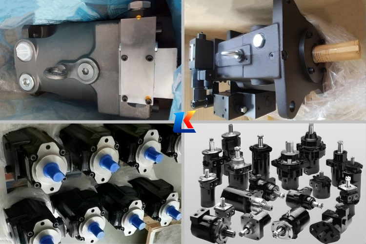
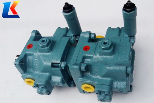
NACHI forming machine PZS series variable piston pump
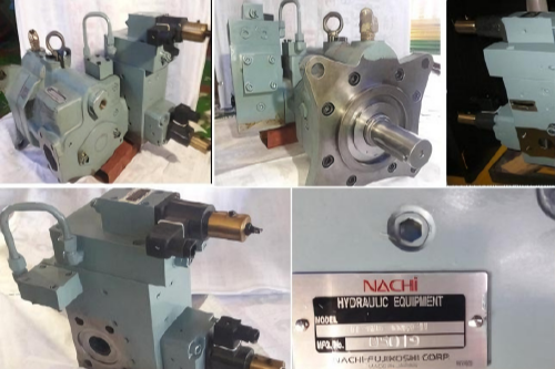
NACHI PZS Series Variable Displacement Piston Pumps for Molding Machines
1. Overview
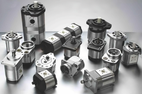
The PZS Series Variable Displacement Piston Pumps, exclusively designed by NACHI for molding machines, integrate high-pressure performance, energy efficiency, and reliable operation. With a displacement range of 70 to 220 cm³/rev, these pumps are engineered to deliver precise hydraulic power, adapting seamlessly to the dynamic operational demands of molding processes. Their variable displacement capability ensures that the discharge rate is maintained at the desired level, significantly enhancing the energy efficiency of hydraulic systems. Suitable for both standalone use and combination with NACHI’s IP internal gear pumps, the PZS Series offers versatile solutions for a wide range of industrial applications, particularly excelling in molding and forging machinery.
2. Core Features
2.1 High Pressure and High Reliability
The PZS Series pumps boast an impressive maximum operating pressure of 28 MPa (286 kgf/cm²) for models 3B and 4B, and 25 MPa (255 kgf/cm²) for models 5B and 6B. This high-pressure capability enables them to handle the rigorous requirements of molding machine operations. The variable displacement design not only ensures optimal energy utilization by adjusting the discharge volume according to system demands but also contributes to stable hydraulic system performance.
2.2 Low Noise and Low Vibration
Adopting a semi-cylindrical swash plate design, the pumps achieve high support rigidity. This structural advantage allows for an increased number of pistons (from 9 to 11) and the integration of optimized valve plates, effectively reducing noise and vibration during operation. This low-noise feature creates a more comfortable and compliant working environment for industrial settings.
2.3 High Reliability and Long Service Life
O-ring seals are utilized on mating surfaces to eliminate oil leakage concerns, ensuring system integrity. The spherical valve plate maintains optimal hydraulic pressure balance, enabling stable operation across a wide range of working conditions and enhancing contamination resistance. These design elements collectively extend the pump’s service life and reduce maintenance frequency.
2.4 Versatile Application Potential
Beyond standalone operation, the PZS Series pumps can be combined with NACHI’s IP series internal gear pumps to form multi-pump configurations. This versatility makes them suitable for a broad spectrum of industrial machinery, including but not limited to molding machines, forging presses, and other general industrial hydraulic systems.
3. Specifications
| Model No. | Displacement (cm³/rev) | Max. Operating Pressure (MPa) | Speed Range (min⁻¹) | Weight (kg) | Pressure Adjustment Range (MPa) |
|---|---|---|---|---|---|
| PZS-3B-70*1-10 | 70 | 28 | 500 – 1800 | 37 | 2 – 28 (20.4 – 286 kgf/cm²) |
| PZS-4B-100*1-10 | 100 | 28 | 500 – 1800 | 58 | 2 – 28 (20.4 – 286 kgf/cm²) |
| PZS-5B-130*1-10 | 130 | 25 | 500 – 1800 | 86 | 2 – 25 (20.4 – 255 kgf/cm²) |
| PZS-6B-180*1-10 | 180 | 25 | 500 – 1800 | 123 | 2 – 25 (20.4 – 255 kgf/cm²) |
| PZS-6B-220*1-10 | 220 | 25 | 500 – 1500 | 126 | 2 – 25 (20.4 – 255 kgf/cm²) |
3.1 Control Options
| Control Type | Symbol | Features |
|---|---|---|
| Pressure Compensation (Manual Control) | N | Automatically reduces output when discharge pressure reaches the set value; remote control is available via auxiliary pilot valve. |
| Dual Pressure & Dual Flow Control | NQ | Achieves 2-stage output variation via a sequence valve, enabling high-low pressure control with one pump for energy-saving in circuits. |
| Electromagnetic Cut-Off Control | RS | Integrates an unloading solenoid valve on the pressure compensation type to minimize energy consumption when hydraulic power is not required. |
| Dual Pressure Control | WS | Obtains two pressure compensation modes via solenoid valve ON/OFF, allowing two pressure controls while maintaining constant actuator speed. |
| Dual Pressure & Dual Flow Control with Electromagnetic Cut-Off | RQS | Adds unloading function to the dual pressure & dual flow control type; unloading can be performed via the on-pump solenoid valve when hydraulic power is not needed (special parts available). |
| Dual Cut-Off Control | CS | Obtains two pressure-flow characteristics via on-pump solenoid valve and output control mechanism (special parts available). |
4. Working Principle
The PZS Series variable displacement piston pump operates based on the reciprocating motion of pistons. The total stroke length L of the piston reciprocation is fixed, determined by the cam lift. The fuel supply per cycle of the piston depends on the fuel supply stroke, which is variable and not controlled by the camshaft. The start of fuel supply does not change with the fuel supply stroke; rotating the piston can change the end of fuel supply, thereby adjusting the fuel supply volume.
4.1 Suction Process
After the convex part of the cam rotates past, the piston moves downward under the action of the spring force, creating a vacuum in the upper space of the piston (called the pumping chamber). When the upper end face of the piston opens the oil suction hole on the piston sleeve, the diesel oil filled in the oil passage of the pump upper body enters the pumping chamber through the oil hole. The piston moves to the bottom dead center, and the suction process ends.
4.2 Discharge Process
The piston moves upward to supply oil. When it moves up to the point where the inclined groove (cut-off edge) on the piston communicates with the oil return hole on the sleeve, the low-pressure oil circuit of the pumping chamber is connected to the central hole, radial hole, and inclined groove of the piston head, resulting in a sudden drop in oil pressure. The delivery valve closes quickly under the action of the spring force to stop oil supply. After that, the piston continues to move upward; when the convex part of the cam rotates past, the piston moves downward again, initiating the next cycle.
4.3 Variable Displacement Control
The variable displacement function is achieved by adjusting the angle of the swash plate. By changing the swash plate angle, the stroke of the pistons is modified, thereby altering the pump’s discharge volume. This adjustment can be controlled through various control options (e.g., pressure compensation, electromagnetic cut-off) to meet the specific flow and pressure requirements of the molding machine’s operating conditions.
5. Application Range
The PZS Series variable displacement piston pumps are specifically designed for molding machines. Additionally, they are suitable for a wide range of general industrial machinery, including forging presses, hydraulic stations, and construction machinery. Their high-pressure performance, energy efficiency, and versatility make them an ideal choice for applications requiring stable and reliable hydraulic power supply.
6. Installation and Operation Notes
6.1 Installation Requirements
- Use a flexible coupling for connecting the drive shaft and the pump shaft to minimize radial and thrust loads on the shaft.
- Ensure the alignment error between the drive shaft and the pump shaft is within 0.05 mm (eccentricity) and 1° (angular error).
- The engagement length between the coupling and the pump shaft should be at least 2/3 of the coupling width.
- Install the pump on a rigid mounting base, ensuring the pump shaft is horizontal.
- The suction side pressure of the pump should be above -0.03 MPa, and the flow velocity at the suction port should not exceed 2 m/sec.
- Use hoses for noise and vibration reduction as recommended.
6.2 Oil Management
- Use high-quality hydraulic oil with a viscosity range of 20 ~ 200 mm²/s during operation; the optimal viscosity range during operation is 20 ~ 50 mm²/s. Generally, R&O type or wear-resistant type hydraulic oil equivalent to ISO VG 32 ~ 68 is recommended.
- Maintain the oil contamination level below NAS 10 grade.
- The operating temperature range of the oil is 5 ~ 60℃. If the oil temperature is below 5℃ during startup, perform warm-up operation at low pressure and low speed until the oil temperature reaches 5℃.
- Use a strainer with a filtration accuracy of approximately 100 μ (150 mesh).
6.3 Startup Notes
- Before starting the pump, fill the pump body with clean hydraulic oil through the oil filler.
- If the motor is started with Δ-Y starting, an unloading circuit is required.
- Confirm that the pump rotation direction is consistent with the arrow indicating the rotation direction (clockwise when viewed from the shaft end).
- Air entrainment in the pump and pipelines can cause noise and vibration. Therefore, perform inching operation with no load on the pump discharge side during startup to bleed air.
- For circuits where air bleeding is difficult during startup, install an air bleed valve.
- Install a check valve on the pump discharge side to prevent reverse rotation and pump damage when the motor is turned off.
6.4 Pressure and Flow Setting
- At the time of shipment, the pump discharge volume is set to maximum and the set pressure to minimum. Adjust the discharge volume and pressure according to the operating conditions.
- Turn the pressure adjustment screw clockwise to increase the pressure; turn the flow adjustment screw clockwise to decrease the discharge volume.
- Tighten the lock nut securely after adjustment.