Sale


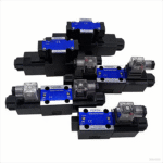
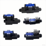
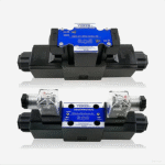

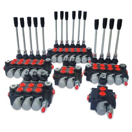
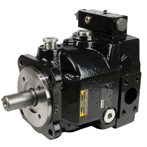
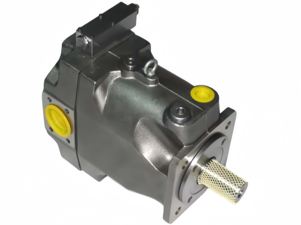
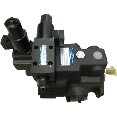
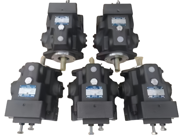
DSG-01 Series Solenoid Operated Directional Valves
DSG-01-2B2-D24-N1-51T;DSG-01-3C4-D24-N1-50;DSG-01-3C60-A110-N1-50;DSG-01-2D2-A240-N1-50;DSG-01-3C12-D24-N1-50
YUKEN DSG-01 series valve is a high-performance solenoid control valve designed for industrial automation and fluid control applications.
Description
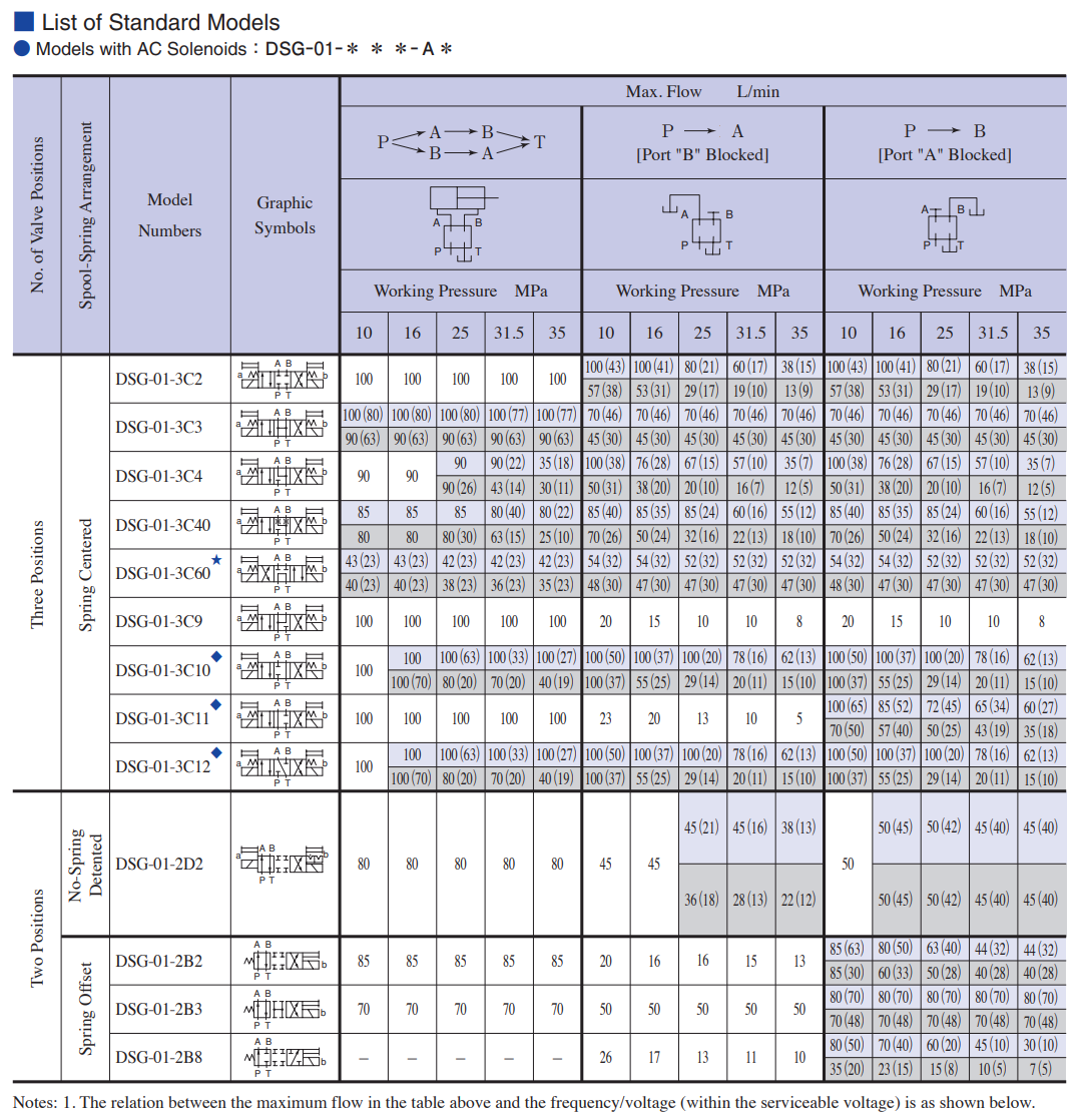
YUKEN DSG-01 Series Solenoid Operated Directional Valves – Specifications & Models
1. Product Overview
The DSG-01 series is a range of 1/8 solenoid operated directional valves developed by YUKEN, featuring a powerful wet-type solenoid and 5-chamber valve body structure. It achieves world-class performance in high pressure, large flow rate, and low pressure drop, while maintaining compact and lightweight characteristics. The series also offers shockless types, multiple electrical connection options, and global certifications for wide applicability.
2. Key Performance Features
-
High Pressure & Large Flow Rate: Maximum operating pressure increased by approximately 10% (from 31.5MPa to 35MPa); allowable back pressure on return line increased by about 30% (from 16MPa to 21MPa); maximum flow rate improved by 60% (from 63L/min to 100L/min) compared to previous models.
-
Low Pressure Drop: Pressure drop reduced by 10% (from 1.0MPa to 0.9MPa) at 60L/min flow rate (spool type 3C2, P→A), contributing to system energy saving.
-
Compact & Lightweight: For dual DC solenoid type, overall length reduced from 210mm to 205mm, weight decreased from 2.2kg to 1.85kg.
-
Stable Operation: Equipped with high-suction solenoid and strong spring, ensuring reliable performance even in contaminated working conditions.
-
Protection Level: Complies with IP65 standard (dust-tight and jet-proof) per IEC Pub.529 and JIS C 0920. DEUTSCH connector type with IP67 protection is also available.
-
Global Certifications: Standard products are CE certified; UL/CSA certified products are available for export (consult YUKEN for details on UL/CSA certified models).
3. Technical Specifications
3.1 Main Parameters
|
Type
|
Model
|
Max. Flow Rate* (L/min)
|
Max. Operating Pressure (MPa)
|
Allowable Return Line Back Pressure (MPa)
|
Max. Switching Frequency (min⁻¹)
|
Mass (kg)
|
|---|---|---|---|---|---|---|
|
Standard Type
|
DSG-01-3C※-※-70, DSG-01-2D2-※-70
|
100
|
35
|
21 (For R solenoid only)
|
300
|
1.85
|
|
Standard Type
|
DSG-01-2B※-※-70
|
120
|
35
|
21 (For R solenoid only)
|
300
|
1.4
|
|
Shockless Type
|
S-DSG-01-3C※-※-70, S-DSG-01-2B2-※-70
|
63
|
25
|
21
|
120
|
1.85 / 1.4
|
|
Shockless Type
|
L-DSG-01-3C※-※-70
|
63
|
25
|
21
|
300 (For R solenoid only)
|
1.85
|
|
Energy-Saving Type*
|
L-DSG-01-2D2-※-70, L-DSG-01-2N※-※-70, L-DSG-01-2B※-※-70
|
40
|
16
|
16
|
120
|
1.85 / 1.4
|
* Notes: 1. For details on energy-saving type, contact YUKEN. 2. Max. flow rate refers to the limit flow without abnormal valve switching, which varies with spool function and operating conditions (see standard function table pages E-15~E-17 for details).
3.2 Base Plate Specifications
|
Base Plate Model
|
Connection Size (Rc)
|
Mass (kg)
|
|---|---|---|
|
DSGM-01-31
|
1/8
|
0.8
|
|
DSGM-01X-31
|
1/4
|
0.8
|
|
DSGM-01Y-31
|
3/8
|
0.8
|
Note: Order base plates according to the table above. If no base plate is used, the mounting surface must be precision machined.
3.3 Standard Solenoid Parameters
|
Type
|
Power Supply
|
Coil Model
|
Frequency (Hz)
|
Rated Voltage (V)
|
Allowable Voltage Range (V)
|
Inrush Current* (A)
|
Holding Current (A)
|
Power (W)
|
|---|---|---|---|---|---|---|---|---|
|
Standard AC Solenoid
|
AC
|
A100
|
50/60
|
100/110
|
80~110 / 90~120
|
2.42 / 2.14
|
0.51 / 0.37
|
– / 44
|
|
A120
|
50/60
|
120
|
108~144 / 96~132
|
2.02 / 1.78
|
0.42 / 0.31
|
– / –
|
||
|
A200
|
50/60
|
200/220
|
160~220 / 180~240
|
1.21 / 1.07
|
0.25 / 0.19
|
– / 22
|
||
|
A240
|
50/60
|
240
|
216~288 / 192~264
|
0.89 / 1.01
|
0.15 / 0.21
|
– / –
|
||
|
R100
|
50/60
|
100
|
90~110
|
–
|
0.33
|
29
|
||
|
R200
|
50/60
|
200
|
180~220
|
–
|
0.16
|
29
|
||
|
DC Solenoid (AC-DC Rectifier Type)
|
DC
|
D12
|
–
|
12
|
10.8~13.2
|
2.45
|
–
|
–
|
|
D24
|
–
|
24
|
21.6~26.4
|
1.23
|
–
|
29
|
||
|
D48
|
–
|
48
|
43.2~52.8
|
0.61
|
–
|
–
|
* Notes: 1. AC shockless type is not equipped with AC solenoid (A※); use AC-DC rectifier type solenoid (R※) for AC power supply in shockless applications. 2. Inrush current is the effective value at maximum stroke. 3. Other coil models are available; contact YUKEN for details. 4. UL certified products are only available for A120 voltage.
4. Model Nomenclature
Example: S DSG -01 -2 B 2 A D24 -C -N*4 -70 -L
|
Position
|
Code
|
Description
|
|---|---|---|
|
1
|
S / F-
|
S: Shockless type; F-: For phosphate ester fluid (special fluororubber seal)
|
|
2
|
DSG
|
Solenoid operated directional valve (base plate mounted type)
|
|
3
|
01
|
Series number
|
|
4
|
2 / 3
|
Number of positions: 2-position / 3-position
|
|
5
|
B / –
|
Spring arrangement: B=Spring return; No mark=Spring centered / Detent (no spring)
|
|
6
|
2 / 3 / 4
|
Spool type (refer to standard function table for details)
|
|
7
|
A / B
|
Solenoid position: A=Power-on position a; B=Power-on position b
|
|
8
|
A100/A120/A200/A240/D12/D24/D48/R100/R200
|
Coil type (AC/DC/AC-DC rectifier type, see Section 3.3 for details)
|
|
9
|
C / –
|
C=40μm filter; No mark=Standard
|
|
10
|
N / N1 / –
|
Electrical connection: N=DIN plug type; N1=DIN plug with power indicator; No mark=Terminal box type
|
|
11
|
70
|
Design number
|
|
12
|
L / –
|
L=Reverse solenoid; No mark=Standard solenoid direction
|
Additional Notes: 1. For valves using center or side positions, refer to page E-18 for details. 2. N1 (DIN plug with power indicator) is not available for AC-DC rectifier type (R※ coils). 3. Special electrical connections (M12-4 pin plug, central DIN plug, DEUTSCH plug) are available; refer to pages E-25~E-26 for details.
5. Optional Configurations
-
Manual Operation Type: Button lock type (for frequent manual operation, with locking mechanism to keep the button in pressed position).
-
Electrical Connection: Terminal box type, DIN plug type, DIN plug with power indicator, M12-4 pin plug (for serial transmission), central DIN plug (reduces wiring time), DEUTSCH plug (IP67 protection).
6. Installation & Usage Precautions
-
Mounting surface must conform to ISO 4401-AB-03-4-A standard when using modular stacking.
-
Hydraulic fluid: Petroleum-based oil (ISO VG 32/46), synthetic fluid (phosphate ester/polyol ester), or water-glycol fluid. Maintain fluid cleanliness at NAS 1638 Grade 12, using a 20μm or finer filter.
-
Recommended fluid viscosity: 15~400 cSt; operating temperature range: -15°C ~ +70°C.
-
When stacking valves, consider maintenance space and follow the specified stacking sequence for pressure reducing valves and pilot check valves.
About brand
Shipping & Delivery