Sale


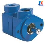
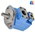
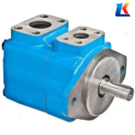

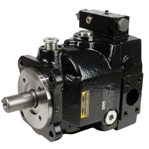
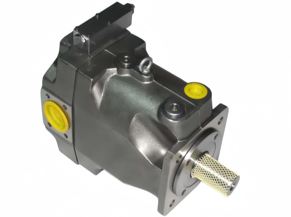
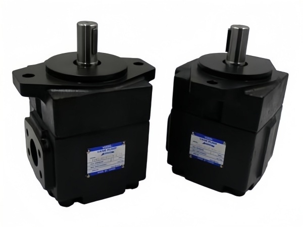
V20-1P18P-1D30 Vickers Hydraulic vane pumps
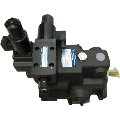
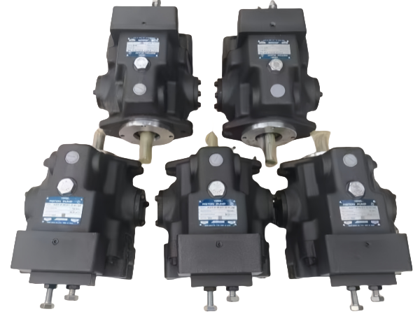
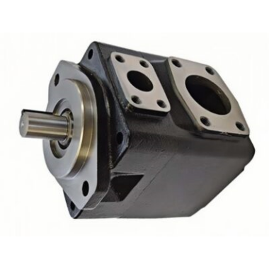
VICKERS vane pumps mainly include the V series, VQ series, VMQ series, V10 & V20 series, and VVS & VVP series.
Whats app: +86 13728707767
E-mail: hyd-sales2009@outlook.com
We are a professional manufacturer of hydraulic pumps, offering a complete range of products. Inquiries are welcome! (#^.^#)
Description
Instruction Manual for Vickers Vane Pump V20-1P18P-1D30
1. Introduction
The Vickers V20-1P18P-1D30 vane pump is a high-performance, medium-low pressure hydraulic component designed for industrial and construction machinery applications. Adopting advanced vane pump technology, it features compact structure, stable operation, low noise, and high volumetric efficiency, making it suitable for various hydraulic systems that require reliable fluid delivery. This manual provides detailed information on the pump’s specifications, installation, operation, maintenance, and troubleshooting to ensure safe and efficient use of the product.
2. Product Overview
2.1 Product Description
The V20-1P18P-1D30 is a fixed-displacement vane pump belonging to Vickers V20 series. Its special oil inlet design ensures balanced oil acceleration and excellent high-speed performance. The pump adopts a modular cartridge design, which simplifies maintenance and replacement of internal components. With 12-vane structure, it operates quietly, making it an ideal choice for indoor industrial environments and heavy-duty construction scenarios.
2.2 Model Explanation
V20-1P18P-1D30
-
V20: Series identifier, indicating Vickers V20 series vane pump
-
1: Body type, standard threaded connection
-
P: Mounting type, standard configuration
-
18: Displacement specification, corresponding to the pump’s displacement parameter
-
P: Shaft type, straight shaft with square key
-
1: Port position, standard configuration
-
D30: Special feature identifier, indicating specific configuration for heavy-duty industrial and construction applications
3. Technical Specifications
|
Parameter
|
Value
|
Unit
|
|
Displacement Range
|
14.5 – 35.8
|
cm³/r (0.88 – 2.18 in³/r)
|
|
Maximum Continuous Pressure
|
172 (2500)
|
bar (psi)
|
|
Peak Pressure
|
190 (2750)
|
bar (psi)
|
|
Maximum Rated Speed
|
3000
|
rpm
|
|
Recommended Speed Range
|
600 – 1800
|
rpm
|
|
Suction Pressure
|
-16.7 ~ +35
|
kPa
|
|
Operating Temperature Range
|
-20 ~ 80
|
℃
|
|
Oil Viscosity Range
|
17 ~ 37
|
mm²/s
|
|
Oil Cleanliness Requirement
|
NAS 8 or higher
|
–
|
|
Weight
|
6.8 – 7.6
|
kg (15 – 16.8 lbs)
|
Note: The specific parameters shall be subject to the nameplate on the pump body, as there may be slight differences due to product optimization.
4. Installation Instructions
4.1 Installation Preparation
-
Check the pump model, specifications, and accessories to ensure they match the purchase order and system requirements. Inspect the pump appearance for damage, deformation, or oil leakage, and check that internal components are intact.
-
Clean the pump body, connecting pipelines, and oil tank thoroughly to remove oil stains, iron filings, and other impurities, avoiding blockage of internal components or wear of vanes and rotors.
-
Prepare installation tools (such as wrenches, coupling alignment tools) and accessories (sealing tape, gaskets, etc.), and ensure the installation site is clean, dry, and well-ventilated, away from high-temperature, vibration sources, or corrosive environments.
4.2 Installation Steps
-
Mount the pump on a firm and rigid base to ensure it can fully absorb vibrations. The mounting surface should be flat, and the fixing bolts should be tightened evenly to prevent pump body deformation.
-
Connect the pump to the motor using a flexible coupling. The concentricity tolerance between the pump shaft and the motor shaft must be less than 0.10 mm (TIR), and the pump shaft shall not bear radial or axial load. The angular deviation shall not exceed 0.5°.
-
If the pump is installed on the tank or above the tank top cover, the height of the pump suction port should be less than 500 mm to avoid insufficient oil suction.
-
After fixing the pump, turn the pump shaft manually to ensure it rotates evenly and flexibly without jamming. Fill the pump with system hydraulic oil through the uppermost port to keep the pump housing full at all times for internal lubrication.
4.3 Pipeline Connection
-
Connect the suction and discharge pipelines according to the pump’s port marks. The suction pipeline should be short and straight, with a diameter not smaller than the pump’s suction port to reduce suction resistance. The discharge pipeline should be equipped with a relief valve, and the regulating pressure of the relief valve shall not exceed the maximum pressure of the pump.
-
Threaded interfaces should be wrapped with sealing tape or coated with sealant (do not let it enter the pump), and flange connections should ensure the gasket is intact to prevent oil leakage. The oil return nozzle should be lower than the fluid surface, with a minimum depth of 50 mm to avoid bubble formation.
-
Install a filter at the pump inlet, 50 mm above the bottom of the tank, with a recommended precision of 100 μm (150 mesh). A precision filter with 25 μm precision is recommended in the system to ensure oil cleanliness.
5. Operation Guidelines
5.1 Pre-Startup Check
-
Check the oil level in the oil tank to ensure it is between the upper and lower limits of the oil level gauge. Check the oil quality to ensure it meets the specified viscosity and cleanliness requirements, and do not mix different types or brands of hydraulic oil.
-
Check all pipeline connections, bolts, and seals for looseness or leakage, and tighten or replace them in time if any problems are found.
-
Check the power supply and electrical connections (if equipped) to ensure the voltage matches the rated value and the wiring is correct and firm. Check the direction of motor rotation to ensure it is consistent with the pump’s rotation direction (right hand rotation when viewed from the shaft end).
5.2 Startup Operation
-
Start the motor at low speed (1/3 of the rated speed) and run it idly for 5 – 10 minutes. During idling, check for abnormal noise, vibration, or oil leakage. If any abnormality is found, stop the machine immediately for inspection.
-
During the initial startup, it may be necessary to bleed air from the pump outlet by loosening an outlet connection until a solid stream of fluid appears, to ensure priming and reduce noise.
-
If the oil viscosity is higher than the suitable range at startup, limit the system pressure to 50% or less of the rated value until the system warms up.
-
Gradually increase the speed and pressure to the rated values, and run the pump continuously for 30 minutes to check the stability of the system pressure, flow rate, and pump temperature. The pump body surface temperature should be kept between 30℃ and 60℃, not exceeding 80℃.
5.3 Operation Precautions
-
During operation, strictly control the working pressure and speed within the rated range, and do not allow long-term operation beyond the rated pressure or speed to avoid overheating, wear, or damage to the pump.
-
Monitor the oil temperature and oil level in real time. If the oil temperature rises sharply, stop the machine immediately to check for oil viscosity, cooling system, or bearing faults. If the oil level is too low, add the same type of hydraulic oil after filtration in time.
-
Listen to the pump operation sound. Normal operation is uniform and low-noise. If abnormal sounds such as squealing, knocking, or vibration occur, stop the machine immediately to check for cavitation, coupling misalignment, or internal component wear.
-
Do not stop the pump suddenly under full load. Reduce the pressure and speed first, then stop the motor to avoid impact damage to the pump and system components.
6. Maintenance and Care
6.1 Daily Maintenance (Daily/Per Shift)
-
Check the oil level and oil quality in the oil tank, and supplement or replace hydraulic oil in time if necessary. Ensure the oil cleanliness is maintained at NAS 8 level or higher.
-
Check the pump body, pipeline connections, and shaft seals for oil leakage. Handle slight leakage in time to avoid accelerated aging of seals.
-
Check the suction filter for blockage. If the vacuum value at the suction port exceeds 0.17 bar or the filter differential pressure alarms, clean or replace the filter element immediately.
6.2 Regular Maintenance
6.2.1 Primary Maintenance (Every 2000 Hours/3 Months)
-
Tighten the connecting bolts of the pump body, motor, and pipeline joints to prevent misalignment and leakage caused by loosening.
-
Check the wear and concentricity of the flexible coupling. Replace the coupling in time if it is aged or eccentric.
-
Test the oil viscosity and water content. If the viscosity deviates from the recommended range or the water content exceeds 0.1%, replace the hydraulic oil immediately.
-
Clean the return oil filter (20 μm precision) and replace the filter element if the differential pressure exceeds the standard. Clean the oil tank filter at the same time.
6.2.2 Secondary Maintenance (Every 6000 Hours/6 Months)
-
Remove the pump inlet cover and check the status of the external seals of the cartridge. Replace them in time if they are aged or deformed.
-
Check the sealing performance of the shaft seal. For double shaft seals, supplement the lubricating oil in the seal cavity. Replace the shaft seal directly if there is oil leakage (it is recommended to replace them as a set).
-
Test the volumetric efficiency of the pump. If the efficiency drops below 85% or the system pressure cannot rise, disassemble the pump to check the wear of internal components.
-
Partially clean the oil tank to remove impurities and oil stains deposited at the bottom.
6.2.3 Tertiary Maintenance (Every 12000 Hours/1 Year)
-
Remove the pump cartridge in a modular way (without disassembling the entire pump body) and check the status of core components: vanes should be free of breakage, deformation, and excessive wear, and can slide flexibly in the rotor slots; the stator inner curved surface should be free of scratches and pits; the rotor slots should be free of wear, and the fit clearance should not exceed 0.03 mm; bearings and pressure plates should be free of clearance and abnormal noise, and bimetallic pressure plates should be free of deformation and cracks.
-
Clean the inside of the cartridge with special hydraulic oil or kerosene, dry it, and reassemble it. Replace all seals (wearing parts, recommended to be replaced as a set).
-
Re-test the concentricity and installation accuracy of the pump. After assembly, perform no-load test run to confirm no leakage or abnormal noise before putting it into load operation.
6.3 Shutdown Protection
6.3.1 Short-Term Shutdown (Within 7 Days)
-
Keep the oil tank full to prevent air from entering the system and generating condensed water.
-
Manually turn the drive shaft 1 – 2 times every day to ensure uniform contact between vanes and the stator surface, avoiding vane jamming due to long-term standing.
-
Close the oil tank breather cap to prevent dust and impurities from entering.
6.3.2 Long-Term Shutdown (More Than 7 Days)
-
Drain the hydraulic oil in the pump and pipelines, flush the inside of the cartridge with special anti-rust oil, and inject an appropriate amount of anti-rust oil to ensure all internal components are immersed.
-
Disassemble the coupling, perform anti-rust treatment on the pump shaft, and wrap it with a protective cover to prevent rust and wear of the shaft journal.
-
Seal the suction and discharge ports with sealant to prevent dust and moisture from entering the pump body.
-
Wipe the pump body surface clean, wrap it for dust and moisture protection, and place it in a dry and ventilated environment.
7. Troubleshooting
|
Fault Phenomenon
|
Possible Causes
|
Solutions
|
|
No oil output or insufficient oil output
|
1. Low oil level or blocked suction filter; 2. Air leakage in the suction pipeline; 3. Vanes stuck or worn; 4. Excessive oil viscosity; 5. Incorrect rotation direction
|
1. Add hydraulic oil and clean/replace the filter element; 2. Check and seal the suction pipeline; 3. Disassemble and clean the pump, replace worn vanes; 4. Replace with suitable viscosity oil; 5. Adjust the motor rotation direction
|
|
Excessive pump noise
|
1. Air in the system; 2. Misalignment of the coupling; 3. Worn bearings or vanes; 4. Blocked suction pipeline; 5. Insufficient oil suction
|
1. Bleed air from the system; 2. Adjust the coupling concentricity; 3. Replace worn bearings or vanes; 4. Clean the suction pipeline; 5. Adjust the pump installation height or oil level
|
|
Oil leakage
|
1. Loose bolts or damaged gaskets; 2. Aged or damaged shaft seal; 3. Excessive system pressure; 4. Damaged pump body or cartridge
|
1. Tighten bolts or replace gaskets; 2. Replace the shaft seal; 3. Adjust the relief valve pressure to the rated value; 4. Repair or replace the pump body or cartridge
|
|
Excessive pump temperature
|
1. Excessive oil viscosity or poor oil quality; 2. Overload operation; 3. Blocked cooling system; 4. Worn internal components; 5. Insufficient lubrication
|
1. Replace with suitable hydraulic oil; 2. Reduce load to rated range; 3. Clean the cooling system; 4. Replace worn components; 5. Check and supplement hydraulic oil
|
|
Unstable system pressure
|
1. Wear of vanes or stator; 2. Leakage in the system; 3. Faulty relief valve; 4. Air in the system
|
1. Replace worn vanes or stator; 2. Check and seal the system; 3. Repair or replace the relief valve; 4. Bleed air from the system
|
8. Safety Precautions
-
Before installation, operation, or maintenance, cut off the power supply and release the system pressure to avoid personal injury or equipment damage caused by accidental startup or high-pressure oil ejection.
-
Operators must be trained and familiar with the pump’s working principle and operation specifications. Do not operate the pump without authorization or modify the system parameters at will.
-
When working with high-pressure hydraulic oil, wear protective equipment (such as gloves, goggles) to prevent oil leakage from scalding or injuring the human body.
-
Do not disassemble or maintain the pump when it is running or under pressure. After shutdown, wait for the oil temperature to drop to normal before operation.
-
Use original accessories and recommended hydraulic oil to ensure the pump’s performance and service life. Do not use inferior accessories or mixed oil products.
-
The pump should be regularly inspected and maintained. If any fault is found, it should be handled in time to avoid expanding the fault and causing more serious damage.
9. Warranty Terms
The Vickers V20-1P18P-1D30 vane pump provides a one-year warranty from the date of purchase. During the warranty period, if the pump fails due to manufacturing defects (excluding damage caused by improper operation, maintenance, installation, or natural wear), the manufacturer will provide free repair or replacement services. For warranty claims, please provide the purchase invoice, product nameplate, and detailed fault description. The warranty does not cover wearing parts (such as vanes, seals, filters) and damage caused by human factors or force majeure.

About brand
Shipping & Delivery