Sale


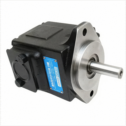
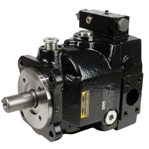
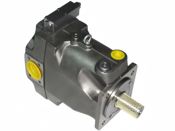
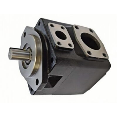
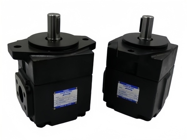
V20-1P21P-1A20 Vickers Hydraulic vane pumps
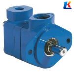
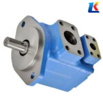
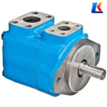
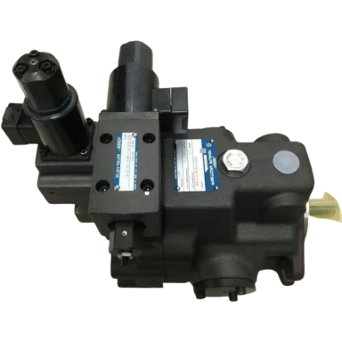
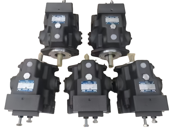
VICKERS vane pumps mainly include the V series, VQ series, VMQ series, V10 & V20 series, and VVS & VVP series.
Whats app: +86 13728707767
E-mail: hyd-sales2009@outlook.com
We are a professional manufacturer of hydraulic pumps, offering a complete range of products. Inquiries are welcome! (#^.^#)
Description
Instruction Manual for Vickers Vane Pump V20-1P21P-1A20
1. Introduction
The Vickers V20-1P21P-1A20 is a high-performance balanced vane pump designed for industrial and mobile hydraulic systems. As a fixed displacement vane pump, it features a compact structure, stable operation, low noise, and long service life, making it suitable for various applications that require reliable hydraulic power supply, such as machine tools, construction machinery, and industrial equipment. This manual provides detailed instructions on the pump’s technical parameters, working principle, installation, operation, maintenance, and troubleshooting to ensure safe and efficient use of the product.
2. Technical Specifications
|
Item
|
Specification
|
|---|---|
|
Model
|
V20-1P21P-1A20
|
|
Pump Type
|
Fixed Displacement Balanced Vane Pump
|
|
Rated Flow
|
6-13 USGPM (22.7-49.2 LPM) @ 1200 RPM
|
|
Rated Pressure
|
155 Bar (2250 PSI)
|
|
Maximum Pressure
|
172 Bar (2500 PSI) (intermittent)
|
|
Rated Speed
|
1200-1800 RPM
|
|
Minimum Starting Speed
|
600 RPM (under standard fluid conditions)
|
|
Fluid Viscosity Range
|
13-54 cSt (70-251 SUS); Recommended: 32 cSt @ 38°C (150 SUS @ 100°F)
|
|
Operating Temperature Range
|
-20°C to 99°C (-4°F to 210°F); Maximum continuous: 65°C (150°F)
|
|
Inlet Pressure
|
0-0.34 Bar (0-5 PSI) gauge; Maximum: 1.38 Bar (20 PSI)
|
|
Fluid Compatibility
|
Petroleum-based hydraulic oil, synthetic fire-resistant fluids (e.g., phosphate esters)
|
|
Mounting Type
|
SAE 2-bolt mounting flange (standard); Foot-mounting bracket (optional)
|
|
Shaft Type
|
Straight with square key (standard)
|
|
Filtration Requirement
|
ISO Cleanliness Code 17/14; Inlet filter: 100 μm (150 mesh); System filter: 25 μm
|
3. Working Principle
The Vickers V20-1P21P-1A20 adopts a balanced vane pump structure, where the internal inlet and outlet pressure chambers are diametrically opposed, balancing pressure-induced radial loads and extending bearing life. The pump consists of key components including a rotor, vanes, cam ring, side plates, and drive shaft.
When the drive shaft rotates, the vanes installed in the rotor’s radial slots slide outward under centrifugal force, closely fitting the inner surface of the cam ring. As the rotor turns, the volume of the chambers formed by the rotor, vanes, and cam ring alternately expands and contracts. During the expansion phase, low-pressure hydraulic fluid is drawn into the pump through the inlet port; during the contraction phase, the fluid is pressurized and discharged through the outlet port, completing the hydraulic power output cycle. The balanced design ensures smooth operation and low noise, while the fixed displacement structure guarantees a stable flow rate proportional to the pump speed.
4. Installation Instructions
4.1 Installation Preparation
-
Inspect the pump for any damage during transportation, such as cracks, oil leaks, or loose components. Check that the model number on the pump cover matches the order and this manual.
-
Clean the installation surface, connecting pipelines, and fluid tank thoroughly to remove dirt, iron filings, and other impurities, which can cause vane wear and pump failure.
-
Prepare the required tools, fasteners, and sealing materials (e.g., O-rings, gaskets) that are compatible with the pump’s operating pressure and fluid type.
-
Ensure the hydraulic fluid meets the specified viscosity and cleanliness requirements. Fill the fluid tank with qualified hydraulic oil to the recommended level.
4.2 Installation Steps
-
Mount the pump on the base or motor flange using the standard SAE 2-bolt mounting flange. Ensure the mounting surface is flat and rigid to absorb vibrations, and tighten the mounting bolts evenly to avoid pump deformation.
-
Connect the pump drive shaft to the power source (motor) using a flexible coupling. The concentricity tolerance between the pump shaft and motor shaft must be less than 0.10 mm (TIR) to avoid radial or axial loads on the pump shaft.
-
Connect the inlet and outlet pipelines. Ensure the pipeline diameter matches the pump’s port size, and the connections are tightly sealed with sealing tape or sealant (do not allow sealant to enter the pump interior). The inlet pipeline should be as short and straight as possible to reduce suction resistance; the oil return pipeline should be inserted below the fluid level (minimum 50 mm) to avoid air entrainment.
-
Install a filter at the pump inlet (100 μm precision) and a full-flow filter in the system (25 μm precision) to maintain fluid cleanliness. A safety relief valve should also be installed in the system, with a set pressure not exceeding the pump’s maximum pressure.
-
If the pump is mounted above the fluid tank, fill the pump with hydraulic fluid through the outlet port to ensure internal lubrication. Turn the pump shaft by hand to check for smooth rotation without jamming.
4.3 Installation Notes
-
Do not install the pump near high-temperature, vibration, or corrosive environments to avoid affecting its service life.
-
The pump’s rotation direction (clockwise or counterclockwise, viewed from the shaft end) must match the power source. To change the rotation direction, the internal components need to be reassembled.
-
The inlet port should not be subjected to excessive vacuum (maximum depression: 0.17 Bar / 5” Hg), and the inlet pressure should not exceed 1.38 Bar (20 PSI) to prevent cavitation.
5. Operation Guide
5.1 Pre-Operation Check
-
Check the hydraulic fluid level in the tank; ensure it is within the specified range. Inspect the fluid for discoloration, turbidity, or contamination, and replace it if necessary.
-
Verify that all pipeline connections are tight and free of leaks. Check the filter status and clean or replace the filter element if clogged.
-
Confirm the pump’s rotation direction is correct. Check that all control valves are in the neutral position to unload the pump during startup.
-
For cold starts (fluid viscosity > 860 cst / 4000 SUS), limit the pump speed and pressure to 50% of the rated values until the system warms up to the recommended operating temperature.
5.2 Startup Operation
-
Start the power source (motor) and run the pump at low speed (600-800 RPM) for 2-3 minutes to prime the pump and bleed entrapped air.
-
Bleed air from the outlet circuit by loosening a connection near the pump until a steady stream of fluid flows out (no air bubbles), then retighten the connection.
-
Gradually increase the speed to the rated value and check the pump’s operation: no abnormal noise, vibration, or oil leaks. Monitor the system pressure and flow rate to ensure they meet the working requirements.
5.3 Normal Operation
-
Maintain the operating temperature between -20°C and 99°C; avoid prolonged operation at temperatures exceeding 65°C to prevent accelerated wear of seals and vane components.
-
Monitor the fluid viscosity regularly; adjust the system temperature if necessary to keep the viscosity within the recommended range.
-
Do not operate the pump at or near rated pressure for extended periods at idle speed, as this may cause localized overheating and damage.
-
Check the pump’s surface temperature during operation; it should be within a safe range (no scalding to the touch).
5.4 Shutdown Operation
-
Reduce the pump speed to low speed and set all control valves to the neutral position to unload the pump.
-
Stop the power source and turn off the system power supply.
-
If the pump will not be used for a long period, drain the hydraulic fluid from the pump and system, clean the tank and pipelines, and refill with new fluid before restarting.
6. Maintenance and Service
6.1 Daily Inspection
-
Check for oil leaks at the pump’s shaft seal, flange connections, and pipeline joints. Tighten loose connections or replace damaged seals promptly.
-
Listen for abnormal noise (e.g., squeaking, knocking) or vibration, which may indicate vane wear, bearing damage, or air entrainment.
-
Monitor the fluid level and cleanliness; add fluid or replace it if necessary. Check the filter pressure gauge (if equipped) and clean or replace the filter element when the pressure exceeds the specified limit.
6.2 Regular Maintenance
|
Maintenance Period
|
Maintenance Content
|
|---|---|
|
Every 250 Hours
|
Clean the inlet filter; check the shaft seal for wear; inspect the fluid viscosity and cleanliness.
|
|
Every 500 Hours
|
Replace the system filter element; check the vane wear status; tighten all mounting and connection bolts.
|
|
Every 1000 Hours
|
Drain and replace the hydraulic fluid; clean the fluid tank; inspect the cam ring and rotor for wear; replace worn vanes and seals.
|
|
Every 2000 Hours
|
Disassemble the pump and inspect all internal components (rotor, cam ring, bearings, side plates); replace damaged or worn parts with original Vickers accessories.
|
6.3 Maintenance Notes
-
Before maintenance, cut off the power supply and relieve system pressure. Hang a “No Operation” sign to ensure safety.
-
Use only original Vickers spare parts to ensure compatibility and maintain pump performance. Do not use inferior or non-compatible parts.
-
When disassembling the pump, follow the correct order and avoid damaging internal components. Clean all parts thoroughly before reassembly and apply a thin layer of hydraulic oil to the moving parts for lubrication.
-
After maintenance, prime the pump and bleed air before restarting. Run the pump at low speed to check for normal operation.
7. Troubleshooting
|
Fault Phenomenon
|
Possible Causes
|
Solutions
|
|---|---|---|
|
No fluid output or insufficient flow
|
1. Low fluid level or clogged inlet filter; 2. Air entrainment in the pump; 3. Worn vanes or cam ring; 4. Incorrect rotation direction; 5. Inlet pipeline leakage
|
1. Add fluid and clean/replace the filter element; 2. Bleed air from the system; 3. Replace worn vanes and cam ring; 4. Correct the rotation direction; 5. Repair the inlet pipeline seal
|
|
System pressure is too low
|
1. Leakage in the system; 2. Worn vane tips or seal components; 3. Incorrect relief valve setting; 4. Excessive pump speed
|
1. Inspect and repair leaking parts; 2. Replace worn vanes and seals; 3. Adjust the relief valve to the specified pressure; 4. Reduce the pump speed to the rated value
|
|
Abnormal noise or vibration
|
1. Air entrainment; 2. Poor shaft alignment; 3. Worn bearings or vanes; 4. Excessive fluid viscosity; 5. Loose mounting bolts
|
1. Bleed air; 2. Adjust shaft alignment; 3. Replace worn bearings and vanes; 4. Adjust system temperature to reduce viscosity; 5. Tighten mounting bolts
|
|
Pump overheating
|
1. High operating temperature; 2. Insufficient fluid or poor fluid quality; 3. Clogged filter or pipeline; 4. Worn internal components causing friction
|
1. Improve heat dissipation; 2. Add or replace fluid; 3. Clean the filter and pipeline; 4. Replace worn internal components
|
|
Oil leakage at the shaft seal
|
1. Worn shaft seal; 2. Shaft damage; 3. Excessive system pressure; 4. Contaminated fluid
|
1. Replace the shaft seal; 2. Repair or replace the shaft; 3. Adjust the relief valve; 4. Replace the hydraulic fluid and clean the system
|
8. Safety Precautions
-
Operators must read this manual thoroughly before using the pump and strictly follow the operation and maintenance instructions.
-
Do not exceed the pump’s rated pressure and speed to avoid equipment damage or personal injury.
-
Avoid contact with high-temperature surfaces of the pump during operation to prevent burns.
-
Do not disassemble or maintain the pump while it is running or under pressure; always cut off power and relieve pressure first.
-
Store hydraulic fluid in a sealed container and keep it away from fire and heat sources. Dispose of used fluid in accordance with local environmental regulations.
-
If the pump malfunctions and cannot be resolved by the troubleshooting steps, stop using it immediately and contact Vickers after-sales service or a professional technician.
About brand
Shipping & Delivery