EATON VICKERS variable piston pump PVXS-250-M-R-DF-0000 manual
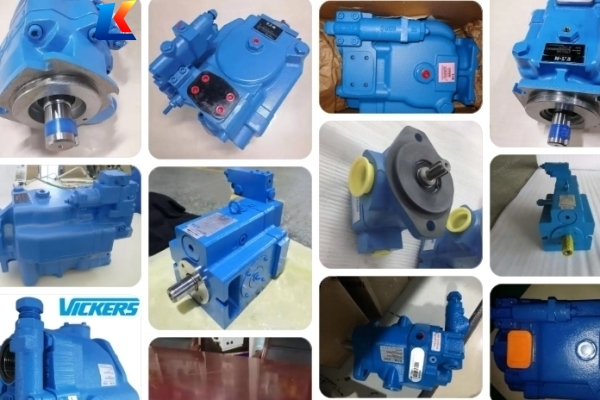
VICKERS Variable Displacement Piston Pump PVXS-250-M-R-DF-0000
1. Product Overview
The EATON VICKERS PVXS-250-M-R-DF-0000 is an open-loop variable displacement axial piston pump, designed for high-pressure industrial applications. With its robust swashplate design, this pump delivers reliable performance, long service life, and excellent responsiveness, making it suitable for use in construction machinery, agricultural equipment, hydraulic systems of heavy industry, and other fields requiring stable and efficient hydraulic power supply. The model features flexible displacement adjustment, compact structure, and strong adaptability to harsh working environments, ensuring optimal operation under various load conditions.
2. Technical Specifications
|
Parameter
|
Specification
|
|---|---|
|
Model
|
PVXS-250-M-R-DF-0000
|
|
Pump Type
|
Open-loop variable displacement axial piston pump
|
|
Rated Pressure (100% duty cycle)
|
350 bar
|
|
Maximum Pressure (per ISO 5598:2008)
|
420 bar
|
|
Maximum Geometric Displacement
|
250 cm³/rev
|
|
Speed Range
|
150 – 1800 rpm (minimum – maximum)
|
|
Inlet Pressure
|
Minimum: 0.85 bar (absolute); Maximum: 10 bar
|
|
Case Pressure (Over Pressure)
|
1.7 bar (at 1800 rpm); 2.1 bar (at 1500 rpm)
|
|
Ambient Temperature Range
|
Minimum: -20°C; Maximum: 50°C
|
|
Hydraulic Fluid Temperature Range
|
Minimum: -25°C (start-up); Maximum: 90°C (continuous operation)
|
|
Fluid Viscosity Range
|
10 – 75 cSt (continuous operation); Maximum: 1000 cSt (start-up)
|
|
Fluid Cleanliness
|
ISO 4406 18/15/13
|
|
Mounting Type
|
Flange or foot-mounted; Combination units are foot-mounted only
|
|
Pipe Connection
|
SAE J518 Code 61 (3 1/2″ – 500); SAE J518 Code 62 (1 1/4″ – 6000)
|
|
Direction of Rotation
|
Clockwise (standard); Counterclockwise available on request
|
|
Weight
|
212 kg
|
|
Moment of Inertia
|
0.146 kg·m²
|
3. Installation Instructions
3.1 Installation Preparation
-
Before installation, check the pump for any damage during transportation, such as cracks, oil leaks, or loose parts. If any damage is found, do not install or operate the pump and contact EATON VICKERS after-sales service immediately.
-
Ensure the installation location is clean, dry, and well-ventilated, with sufficient space for maintenance and operation. Avoid installing the pump in areas with excessive dust, humidity, or high temperature.
-
Prepare the required tools, fasteners, and hydraulic pipelines. The pipelines should be clean, free of debris, and compatible with the pump’s pressure rating. Flush the pipelines before connection to remove any contaminants.
3.2 Mounting Steps
-
Mount the pump to the base or flange using the specified fasteners. Ensure the mounting surface is flat and smooth, and the fasteners are tightened to the recommended torque to prevent vibration during operation.
-
Align the pump shaft with the drive shaft (motor or engine) accurately. The coaxiality error should not exceed 0.1 mm/m to avoid excessive wear on the shaft and bearings.
-
Connect the hydraulic inlet and outlet pipelines to the pump’s ports. Ensure the connections are tight to prevent oil leaks. Use the correct gaskets or seals as specified by EATON VICKERS.
-
Install the required filters, pressure gauges, and other accessories according to the hydraulic system design. Ensure the filter is installed in the inlet pipeline to protect the pump from contaminants.
-
Fill the pump and hydraulic system with the recommended hydraulic oil (refer to Section 4.2 for oil specifications). Bleed the air from the system to avoid cavitation and damage to the pump.
4. Operation Guide
4.1 Pre-Operation Check
-
Check the hydraulic oil level in the system. The oil level should be within the recommended range (between the minimum and maximum marks on the oil tank).
-
Inspect all pipeline connections, fasteners, and seals for looseness or oil leaks. Tighten any loose parts and replace damaged seals immediately.
-
Check the pressure gauge and other instruments to ensure they are functioning normally and calibrated correctly.
-
Verify that the drive system (motor/engine) is operating normally and the direction of rotation is consistent with the pump’s requirements.
4.2 Start-Up Operation
-
Start the drive system (motor/engine) and run it at low speed (150 – 300 rpm) for 2 – 3 minutes to allow the hydraulic oil to circulate and lubricate all components of the pump.
-
Gradually increase the speed to the rated speed (1800 rpm) while monitoring the pressure gauge. The system pressure should be within the normal range, and there should be no abnormal noise, vibration, or oil leaks.
-
Adjust the displacement of the pump according to the system requirements. The displacement can be adjusted by the control mechanism (refer to the control system manual for detailed operation).
4.3 Normal Operation
-
During operation, monitor the system pressure, oil temperature, and pump operation status regularly. The oil temperature should not exceed 90


