A2FM Bent-Axis Fixed Displacement Axial Piston Motor
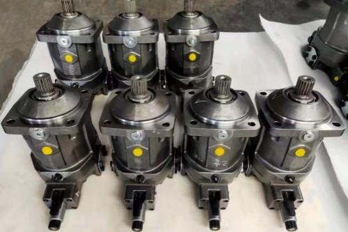
Installation and Operation Manual
(Compatible with Rexroth A2FM Series 61 / 70, 40° bent-axis fixed motor for closed-loop and open-loop circuits, drive applications: travel, winch, slewing)
⚠️ Important Disclaimer: This manual provides general engineering installation guidance. It cannot replace the original manufacturer datasheet or the official manual supplied with the unit. Improper assembly of high-pressure hydraulic components may lead to leakage, motor failure and safety hazards. Commissioning of high-pressure systems must be performed by qualified hydraulic technicians.
Table of Contents
- Safety Instructions
- Inspection on Receipt & Storage
- Pre-Installation Preparation
- Mechanical Mounting (Flange & Shaft Connection, Alignment Requirements)
- Hydraulic Piping Installation, Drain Port Connection (Critical!)
- Seal Selection & Installation
- Flushing, Air Bleeding and Initial Commissioning
- Operational Check Items
- Maintenance & Simple Troubleshooting
- Prohibited Practices
1. Safety Instructions
- System pressure relief! Before any disassembly work, fully depressurize the hydraulic system and cut off the power source to prevent injury from high-pressure oil jetting.
- Operating pressure and rotating speed shall never exceed the peak values marked on the nameplate. Sustained overload and pressure blocking are forbidden.
- The drain line returns directly to the tank. No back pressure is permitted in the drain circuit, otherwise bearings and valve plate will burn out rapidly.
- Hydraulic fluid may reach high temperature during operation. Housing temperature can exceed 80°C; avoid scalding.
- No additional radial load or axial thrust shall be applied to the output shaft (e.g. cantilever-mounted sprockets or pulleys without supporting bearings).
- Disassembly and overhaul must be carried out in a clean environment to prevent contamination entering the motor.
2. Inspection on Receipt & Storage
2.1 Incoming Inspection
- Verify nameplate data: model, displacement, pressure rating, shaft type (keyed / splined), seal material (NBR / FKM), serial number.
- Visual check: housing free of cracks and dents; port plugs and shaft protective cap intact.
- Manually rotate the output shaft: rotation shall be smooth without jamming or abnormal noise. Slight friction sound from piston assembly is normal.
Note: New units are pre-filled with preservative oil. Rotational damping is normal.
2.2 Storage Requirements
- Ambient condition: dry, dust-free, temperature range -20°C ~ +60°C.
- Keep port plugs sealed at all times; apply anti-corrosion protection on the output shaft.
- For storage longer than 6 months: shaft seal replacement is recommended before commissioning. Vertical storage is preferred to avoid one-sided seal aging.
3. Pre-Installation Preparation
- Clean all pipes and manifolds: steel pipes shall be pickled and flushed; hoses shall be free of rubber debris; the hydraulic tank shall be thoroughly cleaned.
- Hydraulic fluid requirements:
- Standard: mineral oil HLP.
- Viscosity: preferred 16~36 mm²/s at operating temperature; allowable range 10~1000 mm²/s.
- Fluid cleanliness: ISO 4406 class 20/18/15 or better. Suction filter, high-pressure filter and return filter are recommended.
- Tools required: torque wrench, hex keys, O-rings, assembly lubricant.
Caution: Do not apply excessive thread locker into oil passages.
- Confirm mounting interface: ISO 3019-2 / SAE flange, verify locating diameter dimensions.
4. Mechanical Mounting
4.1 Flange Fastening
- Clean the motor flange locating shoulder and mating mounting surface, remove burrs and metal chips. Ensure full contact without gaps.
- Tighten bolts diagonally and evenly according to specified torque for the bolt grade. One-sided clamping will deform the housing.
- Mounting attitude: any orientation is acceptable (horizontal, vertical, inclined). The drain port arrangement must ensure the housing is always filled with oil.
- Horizontal mounting: arrange drain port at upper housing side if possible.
- Vertical mounting with output shaft downward: carefully route drain piping to guarantee continuous oil immersion for bearing lubrication.
4.2 Output Shaft Connection (Critical)
✅ Recommended connection: flexible coupling, direct flange coupling to planetary gearbox input.
❌ Not recommended: cantilever-mounted gears or sprockets.
- Alignment tolerance: radial offset ≤0.1 mm; angular misalignment ≤0.2°. Misalignment causes rapid shaft seal leakage and bearing damage.
- Spline / key assembly:
- Apply a thin layer of assembly grease on spline surfaces. Never hammer the shaft into position.
- Parallel key shall fit tightly in the keyway; clearance shall remain at the top of the key to avoid interference.
- Axial restraint: sustained axial pulling or pushing force on the output shaft is prohibited.
Forbidden: Do not strike the end face of the output shaft with a hammer during fitting.
5. Hydraulic Piping Installation (Most Common Error Point for A2FM)
Port definition:
- A, B: Service ports (SAE J518 flange ports). Bi-directional rotation: flow A in / B out or B in / A out.
- T1, T2: Drain ports (housing drain). Use either one drain port to tank and plug the other; both can also be connected in parallel to drain line.
✅ Core Rule: Drain line runs separately and directly to the tank. Do not combine drain line with main return line which carries back pressure. Continuous drain back pressure ≤3 bar, transient peak ≤6 bar. Use short, adequately sized drain piping without restrictions.
Piping Assembly Procedure
- A and B service ports: fit O-rings correctly in grooves without twisting or cutting. Tighten flange bolts diagonally and evenly.
- Piping layout: minimize elbows and high points where air pockets can accumulate.
- Closed-loop circuit: connect A and B to high and low pressure ports of the main pump. Internal charge valve is available on selected versions.
- Open-loop circuit: fit relief protection on return side to suppress pressure shock.
- Pipe support: install pipe clamps to support piping weight. The motor housing must not bear piping load, which causes housing distortion and increased internal leakage.
Factory plastic plugs are only for transit protection and shall not be used for operation.
6. Seals
- NBR (Nitrile): fluid temperature -20 ~ +80°C, for standard mineral oil.
- FKM Fluoroelastomer: fluid temperature -20 ~ +110°C, high temperature resistant, compatible with selected fire-resistant fluids.
- O-ring replacement: replace O-rings whenever pipe joints are disassembled. Avoid sharp tools damaging seals during assembly.
7. Flushing, Air Bleeding and Initial Commissioning
Air bleeding is mandatory for new units or motors after long shutdown. Trapped air inside the housing leads to dry bearing running, abnormal noise and motor burnout.
- Fill the tank with qualified hydraulic fluid to the correct level.
- Low-pressure air bleeding: Run the system at low pressure (<30 bar), jog and reverse A/B repeatedly to slowly rotate the motor. Loosen the drain connection temporarily until bubble-free oil flows out, then retighten.
- No-load running-in: Run at low speed with no load for 5~10 minutes. Check for abnormal noise, vibration and external leakage. Housing temperature rises gradually without sharp overheating.
- Step loading: increase pressure and load in stages, hold each stage for several minutes, verify torque and speed performance.
- Leakage check: minor weeping at static seals may be acceptable. Dripping at shaft seal and flange faces is not permitted.
8. Routine Inspection during Operation
- Housing temperature: continuous operation ≤80°C; transient maximum ≤90°C.
- Noise: smooth hydraulic hum. Stop immediately if high-pitched squealing or metallic knocking occurs.
- Leakage: visually inspect A/B ports, flanges, shaft seal and drain connections.
- Pressure: differential pressure shall not exceed rated pressure on nameplate. Duration of peak pressure must be strictly controlled.
- Rotational speed: never exceed the maximum continuous speed marked on the nameplate. Overspeed damages piston and valve plate.
9. Maintenance Instructions
- Fluid sampling: test viscosity and contamination according to equipment maintenance schedule; replace filter elements periodically.
- External cleaning: keep housing cooling surfaces free of mud and debris for heat dissipation.
- Retightening: recheck flange and pipe bolts after the first shift of operation.
- Overhaul: A2FM is a precision hydraulic component. Field disassembly by users is not recommended. Valve plate, piston set and ball joint require clean bench and special tooling. Unauthorized disassembly voids warranty.
10. Prohibited Practices
❌ Drain port connected to return line with back pressure.
❌ Radial or axial heavy load applied to output shaft.
❌ Long time operation above rated pressure or speed.
❌ Commissioning with contaminated oil and no filtration.
❌ Hammering the motor housing or output shaft.
❌ Starting with trapped pressure inside housing.
❌ Using water-glycol or other special fluids without confirming FKM seal version.
❌ Dry rotation of motor without oil supply.
11. Simple Troubleshooting
| Symptom | Possible Cause |
|---|---|
| Motor fails to rotate or low output torque | Air not fully bled; contamination causing sticking; insufficient pressure differential; relief valve opening prematurely |
| Fast housing temperature rise + abnormal noise | Blocked drain / excessive drain back pressure (most frequent); bearing damage; insufficient lubrication oil |
| Persistent leakage at shaft seal | Misalignment; worn shaft seal; abnormal housing pressure; scratched shaft surface |
| Intermittent vibration & noise | Air ingestion; pump cavitation; pipe resonance |