YUKEN BG-03-3231Y、BG-06-3231Y、BG-02-3231Y
Parameters of YUKEN Hydraulic Valves Models BG-02-3231Y, BG-03-3231Y, BG-06-3231Y
1. Model Interpretation
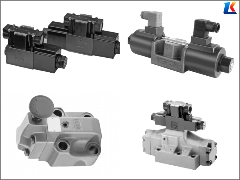
YUKEN BG-02-3231Y, BG-03-3231Y, and BG-06-3231Y belong to the BG series of 3-position 4-way electromagnetic directional control valves. This series is designed for controlling the direction of hydraulic fluid flow in industrial hydraulic systems, featuring reliable operation, compact structure, and strong compatibility. The “3231Y” suffix indicates a consistent functional configuration across the three models, with differences primarily in nominal size and flow capacity to meet diverse system requirements.
1.1 Model Coding Rules (Unified for All Three Models)
-
BG: Series code, indicating YUKEN BG series electromagnetic directional control valve, a 3-position 4-way valve with spring-centered or detent positioning, widely used in general industrial hydraulic systems.
-
02/03/06: Nominal size code, representing the valve’s flow capacity and connection size:
-
BG-02: Nominal size 02, small flow capacity, suitable for small hydraulic systems.
-
BG-03: Nominal size 03, medium flow capacity, suitable for medium-sized hydraulic systems.
-
BG-06: Nominal size 06, large flow capacity, suitable for large hydraulic systems requiring high flow.
-
-
3231: Functional configuration code:
-
First “3”: 3-position valve core.
-
“2”: 4-way flow path design (P, T, A, B ports).
-
Second “3”: Spring-centered positioning (valve core returns to neutral position when power is cut off).
-
“1”: Single solenoid control (one side electromagnetic coil, the other side spring return).
-
-
Y: Solenoid voltage code, indicating AC220V (standard voltage; other voltages such as DC24V are available on request, denoted by “D”).
Note: The three models share the same functional configuration (3-position 4-way, spring-centered, single solenoid, AC220V), with differences only in nominal size, flow capacity, and installation dimensions.
2. Technical Parameters
|
Parameter Item
|
BG-02-3231Y
|
BG-03-3231Y
|
BG-06-3231Y
|
Unit
|
|---|---|---|---|---|
|
Nominal Size
|
02
|
03
|
06
|
–
|
|
Rated Flow
|
10
|
25
|
63
|
L/min
|
|
Maximum Allowable Flow
|
15
|
30
|
80
|
L/min
|
|
Rated Pressure
|
21
|
21
|
21
|
MPa
|
|
Maximum Operating Pressure
|
25
|
25
|
25
|
MPa
|
|
Solenoid Voltage
|
AC220V (50/60Hz)
|
AC220V (50/60Hz)
|
AC220V (50/60Hz)
|
–
|
|
Solenoid Power Consumption
|
28VA
|
45VA
|
80VA
|
VA
|
|
Operating Temperature Range
|
-10 ~ 80
|
-10 ~ 80
|
-10 ~ 80
|
°C
|
|
Applicable Fluids
|
Petroleum-based hydraulic oil, anti-wear hydraulic oil (ISO VG 32-68)
|
Petroleum-based hydraulic oil, anti-wear hydraulic oil (ISO VG 32-68)
|
Petroleum-based hydraulic oil, anti-wear hydraulic oil (ISO VG 32-68)
|
–
|
|
Connection Type
|
Threaded (BSPP)
|
Threaded (BSPP)
|
Flange (ISO 6162)
|
–
|
|
Weight
|
Approx. 1.2
|
Approx. 2.5
|
Approx. 6.8
|
kg
|
3. Product Features
3.1 Common Features (Applicable to All Three Models)
-
Reliable Operation: Adopts high-quality solenoid coil and precision valve core, ensuring stable switching performance and long service life (≥100,000 cycles).
-
Spring-Centered Positioning: The valve core automatically returns to the neutral position when the solenoid is de-energized, preventing system misoperation and ensuring safe operation.
-
Compact Structure: Optimized design, small overall size, easy to install in hydraulic systems with limited space.
-
High Pressure Resistance: Rated pressure up to 21 MPa, suitable for medium and high-pressure hydraulic systems.
-
Wide Compatibility: Compatible with petroleum-based hydraulic oils and anti-wear hydraulic oils, adapting to various industrial working conditions.
-
Easy Maintenance: Modular design, easy to disassemble and replace the solenoid coil and valve core, reducing maintenance time and costs.
3.2 Model-Specific Features
-
BG-02-3231Y:
-
Small nominal size and light weight, suitable for small hydraulic systems with low flow requirements (e.g., small machine tools, precision instruments).
-
Threaded connection, easy to install and disassemble, suitable for compact installation spaces.
-
-
BG-03-3231Y:
-
Medium flow capacity, balancing size and performance, suitable for most general industrial hydraulic systems (e.g., injection molding machines, woodworking machinery).
-
Threaded connection, cost-effective, widely used in medium-sized hydraulic equipment.
-
-
BG-06-3231Y:
-
Large flow capacity, suitable for large hydraulic systems requiring high flow (e.g., hydraulic presses, die-casting machines).
-
Flange connection, strong bearing capacity, stable operation under high flow and high pressure conditions.
-
4. Application Fields
The three models are widely used in various industrial hydraulic systems to control the direction of hydraulic fluid flow, with specific application scenarios differentiated by flow capacity:
-
BG-02-3231Y: Small machine tools (lathes, drilling machines), precision instruments, small packaging machinery, medical equipment, and other small hydraulic systems requiring low flow and precise direction control.
-
BG-03-3231Y: General industrial machinery, small to medium-sized injection molding machines, woodworking machinery, printing machinery, and textile machinery, suitable for medium flow hydraulic systems.
-
BG-06-3231Y: Large hydraulic presses, die-casting machines, metallurgical equipment, construction machinery (small excavators, loaders), and other large hydraulic systems requiring high flow and high pressure.
5. Typical Model Variations
|
Model
|
Nominal Size
|
Solenoid Voltage
|
Connection Type
|
Typical Application
|
|---|---|---|---|---|
|
BG-02-3231Y
|
02
|
AC220V
|
Threaded (BSPP)
|
Small machine tools, precision instruments
|
|
BG-02-3231D
|
02
|
DC24V
|
Threaded (BSPP)
|
Small packaging machinery, medical equipment
|
|
BG-03-3231Y
|
03
|
AC220V
|
Threaded (BSPP)
|
Medium-sized injection molding machines
|
|
BG-06-3231Y
|
06
|
AC220V
|
Flange (ISO 6162)
|
Hydraulic presses, die-casting machines
|
6. Installation and Operation Notes
-
Before installation, check the valve model, nominal size, and solenoid voltage to ensure they match the system requirements.
-
Install the valve in a dry, clean, and well-ventilated environment, avoiding direct sunlight and high-temperature radiation.
-
Ensure the direction of the fluid flow (P, T, A, B ports) is consistent with the valve’s marking; reverse flow will cause valve failure.
-
Tighten the connection bolts (threaded or flange) according to the specified torque to prevent oil leakage; over-tightening may damage the valve body.
-
The solenoid coil should be installed correctly, ensuring good contact and avoiding loose connections that may cause coil burnout.
-
Maintain hydraulic oil cleanliness at NAS 7 level or higher, and install a high-precision filter (≥10 μm) in the system to prevent impurities from damaging the valve core.
-
The operating temperature of the hydraulic oil should be controlled within -10°C to 80°C; excessive temperature will affect the service life of the seal and solenoid coil.
-
Regularly inspect the valve for oil leakage, abnormal noise, and slow switching; if any abnormality is found, stop the system immediately for inspection and maintenance.
-
When replacing the solenoid coil, cut off the power supply first to avoid electric shock; use only genuine YUKEN replacement parts.
-
Do not exceed the maximum allowable pressure and flow specified in the technical parameters to prevent valve damage.


