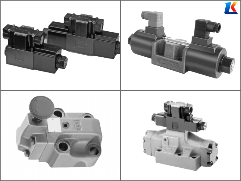
YUKEN Relief Valves S-BSG-01、S-BSG-03、S-BSG-06
Parameters of YUKEN Low Noise Solenoid Controlled Relief Valves Models S-BSG-01, S-BSG-03, S-BSG-06
1. Model Interpretation
YUKEN S-BSG-01, S-BSG-03, S-BSG-06 are low noise type solenoid controlled pilot operated relief valves, which combine a low-noise pilot operated relief valve with a solenoid operated directional valve. They are designed for no-load pump operation via electric signals or, together with a remote control relief valve, for two or three pressure control of hydraulic systems. The S-BSG series is the sub-plate mounting version (G), with different nominal sizes (01/03/06) providing varying flow capacities to meet diverse industrial hydraulic system requirements.
1.1 Model Coding Rules (Unified for All Three Models)
-
S: Low noise type, reduces operating noise by up to 10dB compared to conventional models.
-
BS: Solenoid controlled relief valve series code, indicating integration of relief valve and solenoid directional valve.
-
G: Mounting type code, indicating sub-plate mounting (ISO 4401 standard).
-
01/03/06: Nominal size code, representing the valve’s flow capacity and connection size:
-
S-BSG-01: Nominal size 01, smallest flow capacity, suitable for small hydraulic systems with low flow requirements (minimum flow ≥ 3 L/min).
-
S-BSG-03: Nominal size 03, small to medium flow capacity, suitable for small to medium-sized hydraulic systems (minimum flow ≥ 5 L/min).
-
S-BSG-06: Nominal size 06, medium to large flow capacity, suitable for medium to large-sized hydraulic systems (minimum flow ≥ 5 L/min).
-
-
Additional Code Explanation: Complete model typically includes vent type, high venting pressure feature, solenoid specifications, and design number:
-
Vent type: 2B (single solenoid, spring return), 3B (double solenoid).
-
High venting pressure feature: V (high venting pressure type, reduces changeover time from unloading to onloading).
-
Solenoid voltage: A (AC voltage, e.g., A220 for AC220V), D (DC voltage, e.g., D24 for DC24V).
-
Design number: 47/48/50/51, indicating specific design variations (installation dimensions remain unchanged for minor design changes).
-
Note: The three models share the same basic structure (sub-plate mounted, low noise, solenoid controlled pilot operated relief valve), with differences primarily in nominal size, flow capacity, maximum operating pressure, and installation dimensions.
2. Technical Parameters
|
Parameter Item
|
S-BSG-01
|
S-BSG-03
|
S-BSG-06
|
Unit
|
|---|---|---|---|---|
|
Nominal Size
|
01
|
03
|
06
|
–
|
|
Valve Type
|
Low Noise Solenoid Controlled Pilot Operated Relief Valve
|
–
|
||
|
Mounting Type
|
Sub-plate Mounted (ISO 4401-01/03/06)
|
–
|
||
|
Maximum Operating Pressure
|
25
|
25
|
25
|
MPa
|
|
Pressure Adjustment Range
|
0.6-7, 3.5-21
|
0.6-7, 3.5-21, 7-31.5
|
3.5-21, 7-31.5
|
MPa
|
|
Rated Flow
|
16
|
63
|
160
|
L/min
|
|
Maximum Allowable Flow
|
20
|
80
|
200
|
L/min
|
|
Minimum Recommended Flow
|
3
|
5
|
5
|
L/min
|
|
Pressure Setting Accuracy
|
±5%
|
±5%
|
±5%
|
of Set Pressure
|
|
Operating Temperature Range
|
-10 ~ 80
|
-10 ~ 80
|
-10 ~ 80
|
°C
|
|
Applicable Fluids
|
Petroleum-based hydraulic oil, anti-wear hydraulic oil (ISO VG 32-68)
|
–
|
||
|
Oil Cleanliness Requirement
|
NAS 7 or higher (≥10 μm filtration)
|
–
|
||
|
Solenoid Voltage Options
|
AC110V, AC220V, DC24V (standard), DC12V
|
–
|
||
|
Solenoid Power Consumption
|
28VA (AC), 25W (DC)
|
45VA (AC), 35W (DC)
|
60VA (AC), 45W (DC)
|
VA/W
|
|
Weight
|
Approx. 1.2
|
Approx. 5.2
|
Approx. 11.8
|
kg
|
3. Product Features
3.1 Common Features (Applicable to All Three Models)
-
Low Noise Operation: Special design reduces operating noise by up to 10dB, ideal for noise-sensitive environments.
-
Solenoid Controlled: Enables remote control of pressure settings and system unloading via electric signals, improving automation and energy efficiency.
-
Pilot Operated Design: High pressure control accuracy (±5% of set pressure), stable performance, and low pressure drop at full flow compared to direct acting relief valves.
-
Sub-plate Mounted: Easy integration into hydraulic manifolds, space-saving, and convenient for system layout optimization.
-
Remote Control Capability: Equipped with remote control port (X), allowing remote pressure adjustment and system unloading through external control valves.
-
Wide Pressure Range: Multiple pressure adjustment ranges available (0.6-31.5MPa), suitable for various pressure requirements in industrial applications.
-
High Reliability: Adopts high-quality materials and precision manufacturing processes, ensuring long service life (≥50,000 cycles) and stable operation under harsh conditions.
-
High Venting Pressure Option: V-type available for reducing changeover time from unloading to onloading.
3.2 Model-Specific Features
-
S-BSG-01:
-
Smallest nominal size and light weight, suitable for small hydraulic systems (e.g., small machine tools, precision instruments) requiring low flow and low to medium pressure control.
-
Lower maximum flow (up to 20 L/min), ideal for systems with limited flow requirements.
-
Minimum recommended flow of 3 L/min to ensure stable pressure settings.
-
-
S-BSG-03:
-
Balanced size and performance, suitable for most general industrial hydraulic systems (e.g., small injection molding machines, woodworking machinery).
-
Medium flow capacity (up to 80 L/min), cost-effective, and widely used in medium-sized hydraulic equipment.
-
Minimum recommended flow of 5 L/min to ensure stable pressure settings.
-
-
S-BSG-06:
-
Large flow capacity (up to 200 L/min), suitable for medium to large hydraulic systems (e.g., medium-sized hydraulic presses, plastic machinery).
-
Higher power consumption for solenoid, suitable for systems requiring higher switching capacity.
-
Minimum recommended flow of 5 L/min to ensure stable pressure settings.
-
4. Application Fields
The three models are widely used in various industrial hydraulic systems for pressure control, unloading, and multi-pressure control applications, with specific application scenarios differentiated by flow capacity and pressure requirements:
-
S-BSG-01: Small machine tools, precision instruments, medical equipment, small packaging machinery, and other small hydraulic systems requiring low flow, precise pressure control, and low noise operation.
-
S-BSG-03: General industrial machinery, small to medium-sized injection molding machines, woodworking machinery, printing machinery, and textile machinery requiring medium flow and remote pressure control.
-
S-BSG-06: Medium-sized hydraulic presses, plastic machinery, rubber processing equipment, and other medium to large hydraulic systems requiring high flow, high pressure protection, and remote control capabilities.
5. Typical Model Variations
|
Model
|
Nominal Size
|
Vent Type
|
High Venting Pressure
|
Solenoid Voltage
|
Pressure Range
|
Max. Flow
|
Typical Application
|
|---|---|---|---|---|---|---|---|
|
S-BSG-01-2B3B-D24-N-50
|
01
|
2B (Single Solenoid)
|
No
|
DC24V
|
3.5-21 MPa
|
20 L/min
|
Small machine tools (low noise requirement)
|
|
S-BSG-03-V-2B3B-A220-N-48
|
03
|
2B (Single Solenoid)
|
Yes (V-type)
|
AC220V
|
7-31.5 MPa
|
80 L/min
|
Small injection molding machines (fast response)
|
|
S-BSG-06-3B3B-D24-N-51
|
06
|
3B (Double Solenoid)
|
No
|
DC24V
|
3.5-21 MPa
|
200 L/min
|
Medium hydraulic presses (multi-pressure control)
|
6. Installation and Operation Notes
-
Before installation, check the valve model, nominal size, pressure range, solenoid voltage, and design code to ensure they match the system requirements.
-
Clean the mounting surface and ensure no debris or contaminants are present to prevent leakage and valve damage.
-
Use the correct mounting bolts and torque specifications (refer to YUKEN technical documentation) to ensure proper sealing and prevent valve body deformation.
-
Connect the hydraulic lines correctly: P (pressure port), T (tank port), X (remote control port – plug if not used).
-
Ensure the remote control port (X) is properly sealed if not in use to prevent oil leakage and pressure loss.
-
Adjust the pressure setting gradually using the adjustment handle, ensuring the system pressure does not exceed the maximum operating pressure of the valve. One collar is equivalent to 10 MPa (1450 PSI).
-
Maintain hydraulic oil cleanliness at NAS 7 level or higher, and install a high-precision filter (≥10 μm) in the system to prevent impurities from damaging the pilot valve and main valve core.
-
The operating temperature of the hydraulic oil should be controlled within -10°C to 80°C; excessive temperature will affect the service life of the seal and valve performance.
-
Ensure the minimum flow requirement is met (01: ≥3 L/min, 03/06: ≥5 L/min) to maintain stable pressure settings.
-
Regularly inspect the valve for oil leakage, abnormal noise, and pressure fluctuations; if any abnormality is found, stop the system immediately for inspection and maintenance.
-
When replacing parts, use only genuine YUKEN replacement parts to ensure compatibility and maintain valve performance.
-
Do not exceed the maximum allowable pressure and flow specified in the technical parameters to prevent valve damage and system failure.
-
The solenoid coil should be installed correctly, ensuring good contact and avoiding loose connections that may cause coil burnout.


