DAIKIN Variable Displacement Piston Pump V38A3RX-95
Instruction Manual for DAIKIN Variable Displacement Piston Pump V38A3RX-95
Document No.: DAIKIN-V38A3RX-95-EN-001 | Edition: 1.0 | Date: 2026-03-25
1. Introduction
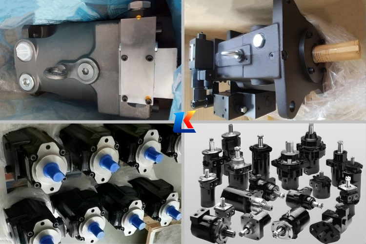
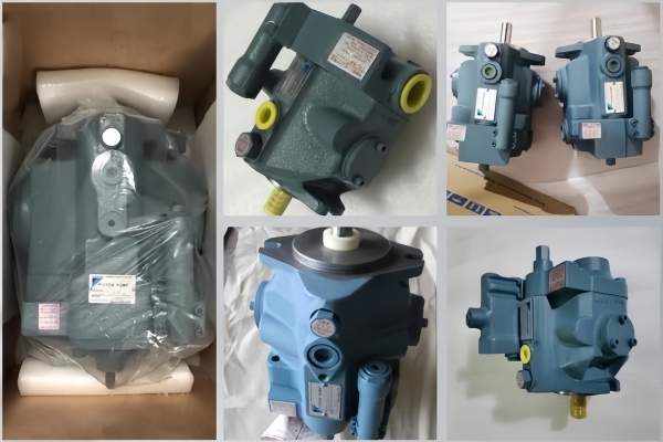
The DAIKIN V38A3RX-95 is a high-performance axial piston variable displacement pump belonging to DAIKIN’s V-Series, specifically engineered for medium-to-high pressure industrial hydraulic systems. It adopts advanced swash-plate structure and built-in pressure compensator control, featuring low noise operation across the entire pressure range, minimal power loss, high volumetric efficiency, excellent responsiveness and stability. With its compact and robust cast-iron construction, this pump is widely applicable to machine tools, forging presses, plastic molding machines, construction machinery and other heavy-duty equipment that requires reliable and efficient fluid power transmission. This manual provides comprehensive guidance on the pump’s specifications, installation, operation, maintenance and troubleshooting, aiming to ensure safe, reliable and long-term service of the product.
2. Product Overview
2.1 Product Description
The V38A3RX-95 is a swash-plate type variable displacement piston pump with integrated pressure compensator control. Its key design advantages ensure optimal performance in industrial applications: low noise emission throughout the full pressure range, reduced oil temperature rise due to minimal power loss, high responsiveness to system pressure changes, and strong structural durability thanks to cast-iron material. The pump adopts a side-port piping configuration for convenient installation and maintenance, and features clockwise rotation when viewed from the shaft end. It is designed with a compact structure, which saves installation space while ensuring stable operation even under harsh working conditions, and offers easy maintenance to minimize downtime.
2.2 Model Explanation
V38A3RX-95
-
V38: Series and displacement class, indicating DAIKIN V-Series variable displacement piston pump with a theoretical displacement of approximately 37.7 cm³/rev (cc/rev).
-
A3: Control type, representing pressure compensator control, which automatically adjusts the pump displacement according to the system pressure demand to achieve energy saving.
-
RX: Mounting and port configuration, indicating side-port piping and standard mounting dimensions for easy integration into various hydraulic systems.
-
95: Special configuration identifier, representing the standard industrial configuration optimized for medium-to-high pressure working scenarios.
3. Technical Specifications
|
Parameter
|
Value
|
Unit
|
|
Theoretical Displacement
|
37.7
|
cm³/rev (cc/rev)
|
|
Maximum Continuous Pressure
|
25 (3626)
|
MPa (psi)
|
|
Peak Pressure
|
28 (4061)
|
MPa (psi)
|
|
Speed Range
|
500 – 1800
|
rpm
|
|
Maximum Discharge Flow (at 1800 rpm)
|
68.0
|
L/min
|
|
Rotation Direction
|
Clockwise (viewed from shaft end)
|
–
|
|
Operating Temperature Range
|
-20 ~ 80
|
℃
|
|
Oil Viscosity Range
|
10 ~ 400
|
mm²/s (cSt)
|
|
Oil Cleanliness Requirement
|
NAS 7 or higher
|
–
|
|
Weight
|
24.4 – 26.0
|
kg (53.8 – 57.3 lbs)
|
|
Overall Dimensions (L×W×H)
|
198 × 289.5 × 189
|
mm
|
|
Noise Level (at 1800 rpm, full load)
|
≤ 72
|
dB(A)
|
Note: The specific parameters shall be subject to the nameplate on the pump body, as there may be slight differences due to product optimization and batch production. For special working conditions, please consult DAIKIN authorized dealers or the manufacturer directly.
4. Installation Instructions
4.1 Installation Preparation
-
Check the pump model, specifications and accessories to ensure they match the purchase order and hydraulic system requirements. Inspect the pump appearance for damage, deformation or oil leakage, and confirm that internal components are intact and free from foreign objects.
-
Clean the pump body, connecting pipelines and oil tank thoroughly to remove oil stains, iron filings, dust and other impurities, so as to avoid blockage of internal components, wear of pistons, swash plates and other core parts, and ensure the cleanliness of the hydraulic system.
-
Prepare necessary installation tools (such as wrenches, coupling alignment tools, torque wrenches) and accessories (sealing gaskets, sealing tape, anti-rust oil). Ensure the installation site is clean, dry and well-ventilated, away from high-temperature heat sources, strong vibration sources and corrosive environments.
-
Check the mounting base to ensure it is firm, rigid and flat, with sufficient bearing capacity to absorb vibration during pump operation and prevent pump body deformation.
4.2 Installation Steps
-
Mount the pump on the prepared base, place the gasket between the pump flange and the base, and tighten the fixing bolts evenly with a torque wrench according to the specified torque (refer to the nameplate for torque value) to avoid uneven stress and pump body deformation.
-
Connect the pump to the motor using a flexible coupling. The concentricity tolerance between the pump shaft and the motor shaft must be less than 0.10 mm (TIR), and the angular deviation shall not exceed 0.5° to prevent additional radial load on the pump shaft, which may cause bearing wear and noise increase.
-
Ensure the pump rotation direction is consistent with the motor rotation direction (clockwise when viewed from the shaft end). Incorrect rotation direction will cause no oil output, overheating and damage to internal components.
-
After fixing the pump and connecting the coupling, turn the pump shaft manually for 2-3 full rotations to ensure it rotates flexibly and evenly without jamming. Fill the pump with clean hydraulic oil that meets the requirements through the oil filling port to ensure all internal components are fully lubricated before startup.
4.3 Pipeline Connection
-
Connect the suction and discharge pipelines according to the pump’s port marks (IN for suction, OUT for discharge). The suction pipeline should be short, straight and smooth, with a diameter not smaller than the pump’s suction port to reduce suction resistance and avoid cavitation. The discharge pipeline should be equipped with a relief valve, and the regulating pressure of the relief valve shall not exceed the maximum continuous pressure of the pump.
-
Threaded interfaces should be wrapped with sealing tape or coated with appropriate sealant (do not let sealant enter the pump body), and flange connections should ensure the gasket is intact and correctly installed to prevent oil leakage. The oil return pipeline should be connected to the oil tank, and the oil return nozzle should be lower than the oil level to avoid air entering the system and generating bubbles.
-
Install a coarse filter (precision 100 μm) at the pump inlet to prevent large impurities from entering the pump. A fine filter (precision 25 μm) is recommended in the system to ensure the oil cleanliness meets NAS 7 level or higher. Install a pressure gauge and a temperature gauge on the discharge pipeline to monitor the system pressure and oil temperature in real time.
-
After pipeline connection, perform a pressure test (test pressure is 1.2 times the maximum continuous pressure) to check for pipeline leakage. If leakage is found, stop the test immediately, release the pressure and repair it.
5. Operation Guidelines
5.1 Pre-Startup Check
-
Check the oil level in the oil tank to ensure it is between the upper and lower limits of the oil level gauge. Check the oil quality to ensure it meets the specified viscosity and cleanliness requirements, and do not mix different types or brands of hydraulic oil.
-
Check all pipeline connections, bolts and seals for looseness or leakage. Tighten loose bolts in time and replace damaged seals or gaskets.
-
Check the power supply and electrical connections to ensure the voltage matches the motor rated value and the wiring is correct and firm. Confirm the motor rotation direction is consistent with the pump’s rotation direction.
-
Check the pressure compensator and other control components to ensure they are in normal working condition, without jamming or damage.
-
Turn the pump shaft manually again to confirm it rotates flexibly without jamming, and check that the oil filling port is unobstructed.
5.2 Startup Operation
-
Start the motor at low speed (1/3 of the rated speed) and run it idly for 5-10 minutes. During idling, check for abnormal noise, vibration or oil leakage. If any abnormality is found, stop the machine immediately, cut off the power supply and conduct inspection.
-
During the initial startup, it may be necessary to bleed air from the pump outlet by loosening an outlet connection until a solid stream of oil appears, to ensure the pump is fully primed and reduce noise and cavitation.
-
If the oil viscosity is too high at startup (e.g., in low-temperature environments), limit the system pressure to 50% or less of the rated value and run the pump at low speed until the system oil temperature rises to the normal range (30-60℃).
-
Gradually increase the motor speed and system pressure to the rated values, and run the pump continuously for 30 minutes. During this period, monitor the pump temperature, system pressure and flow rate to ensure they are stable. The pump body surface temperature should not exceed 80℃.
5.3 Operation Precautions
-
During operation, strictly control the working pressure and speed within the rated range. Do not allow long-term operation beyond the rated pressure or speed, as this will cause overheating, accelerated wear of internal components and shorten the pump service life.
-
Monitor the oil temperature and oil level in real time. If the oil temperature rises sharply (exceeding 80℃), stop the machine immediately to check for oil viscosity, cooling system failure or internal component wear. If the oil level is too low, add the same type of hydraulic oil after filtration in time.
-
Listen to the pump operation sound. Normal operation is uniform and low-noise. If abnormal sounds such as squealing, knocking or vibration occur, stop the machine immediately to check for cavitation, coupling misalignment, bearing wear or internal component damage.
-
Do not stop the pump suddenly under full load. Reduce the system pressure and motor speed first, then stop the motor to avoid impact damage to the pump and system components.
-
During operation, avoid frequent start-stop of the pump. The interval between two starts should be no less than 3 minutes to prevent damage to the motor and pump due to frequent load changes.
6. Maintenance and Care
6.1 Daily Maintenance (Daily/Per Shift)
-
Check the oil level and oil quality in the oil tank. If the oil becomes turbid, discolored or has impurities, replace it in time. Ensure the oil cleanliness is maintained at NAS 7 level or higher.
-
Check the pump body, pipeline connections and shaft seals for oil leakage. Handle slight leakage in time to avoid accelerated aging of seals and oil waste.
-
Check the suction filter for blockage. If the filter differential pressure exceeds 0.15 MPa or the vacuum value at the suction port is too high, clean or replace the filter element immediately.
-
Monitor the pump operation status, including noise, vibration and temperature, and record the operation parameters for future reference.
6.2 Regular Maintenance
6.2.1 Primary Maintenance (Every 2000 Operating Hours/3 Months)
-
Tighten the connecting bolts of the pump body, motor, coupling and pipeline joints to prevent misalignment and leakage caused by loosening.
-
Check the wear and concentricity of the flexible coupling. Replace the coupling in time if it is aged, cracked or eccentric.
-
Test the oil viscosity and water content. If the viscosity deviates from the recommended range or the water content exceeds 0.1%, replace the hydraulic oil and clean the oil tank.
-
Clean the return oil filter (25 μm precision) and replace the filter element if the differential pressure exceeds the standard. Clean the oil tank filter and remove impurities deposited at the bottom of the tank.
-
Check the pressure compensator for jamming or wear, and clean it if necessary to ensure its normal operation.
6.2.2 Secondary Maintenance (Every 6000 Operating Hours/6 Months)
-
Disassemble the pump inlet and outlet flanges, and check the status of the pump shaft seal. Replace the shaft seal if there is oil leakage or wear (it is recommended to replace them as a set).
-
Check the wear of the pump’s internal components (pistons, cylinder block, swash plate, valve plate). If there are scratches, wear or deformation, repair or replace them in time.
-
Test the volumetric efficiency of the pump. If the efficiency drops below 85% or the system pressure cannot reach the rated value, disassemble the pump for thorough inspection and maintenance.
-
Clean the inside of the pump body with clean hydraulic oil or kerosene, dry it, and apply anti-rust oil to the internal components before reassembly.
-
Check the cooling system (if equipped) for blockage or leakage, and clean or repair it in time to ensure the oil temperature is controlled within the normal range.
6.2.3 Tertiary Maintenance (Every 12000 Operating Hours/1 Year)
-
Completely disassemble the pump, check all internal components (pistons, cylinder block, swash plate, valve plate, bearings, seals) for wear, deformation or damage, and replace all worn parts and seals (recommended to use DAIKIN original accessories).
-
Check the pump shaft for wear, bending or deformation. If any problem is found, repair or replace the pump shaft.
-
Reassemble the pump according to the installation specifications, and ensure the fit clearance of each component meets the requirements. After reassembly, perform a no-load test run for 30 minutes, then a load test run to confirm no leakage, abnormal noise or pressure instability.
-
Completely clean the oil tank, replace the hydraulic oil and all filter elements, and check the entire hydraulic system for leakage and performance stability.
6.3 Shutdown Protection
6.3.1 Short-Term Shutdown (Within 7 Days)
-
Keep the oil tank full to prevent air from entering the system and generating condensed water, which may cause rust of internal components.
-
Manually turn the pump shaft 1-2 times every day to ensure uniform contact between internal components and avoid jamming due to long-term standing.
-
Close the oil tank breather cap to prevent dust and impurities from entering the system, and keep the installation site clean and dry.
6.3.2 Long-Term Shutdown (More Than 7 Days)
-
Drain the hydraulic oil in the pump and pipelines, flush the inside of the pump and system with special cleaning oil, then inject an appropriate amount of anti-rust oil to ensure all internal components are immersed in anti-rust oil.
-
Disassemble the coupling, perform anti-rust treatment on the pump shaft, and wrap it with a protective cover to prevent rust and wear of the shaft journal.
-
Seal the pump’s suction and discharge ports with sealing plugs or sealant to prevent dust and moisture from entering the pump body.
-
Wipe the pump body surface clean, wrap it with moisture-proof and dust-proof materials, and place it in a dry, ventilated and non-corrosive environment. Avoid placing heavy objects on the pump to prevent deformation.
7. Troubleshooting
|
Fault Phenomenon
|
Possible Causes
|
Solutions
|
|
No oil output or insufficient oil output
|
1. Low oil level or blocked suction filter; 2. Air leakage in the suction pipeline; 3. Incorrect rotation direction; 4. Pistons or swash plate worn; 5. Pressure compensator jammed; 6. Excessive oil viscosity
|
1. Add hydraulic oil and clean/replace filter element; 2. Check and seal suction pipeline; 3. Adjust motor rotation direction; 4. Replace worn pistons or swash plate; 5. Clean pressure compensator; 6. Replace with suitable viscosity oil
|
|
Excessive pump noise
|
1. Air in the system; 2. Coupling misalignment; 3. Bearing wear; 4. Cavitation due to insufficient suction; 5. Internal components worn or loose; 6. Blocked suction pipeline
|
1. Bleed air from the system; 2. Adjust coupling concentricity; 3. Replace worn bearings; 4. Increase oil level and clean suction pipeline; 5. Tighten loose components or replace worn parts; 6. Clean suction pipeline
|
|
Oil leakage
|
1. Loose bolts or damaged gaskets; 2. Aged or damaged shaft seal; 3. Excessive system pressure; 4. Damaged pump body or internal components; 5. Poor pipeline connection
|
1. Tighten bolts or replace gaskets; 2. Replace shaft seal; 3. Adjust relief valve pressure to rated value; 4. Repair or replace pump body/components; 5. Reconnect pipelines and strengthen sealing
|
|
Excessive pump temperature
|
1. Overload operation; 2. Poor oil quality or excessive viscosity; 3. Blocked cooling system; 4. Internal components worn (increased friction); 5. Insufficient lubrication
|
1. Reduce load to rated range; 2. Replace hydraulic oil; 3. Clean cooling system; 4. Replace worn components; 5. Check and supplement hydraulic oil
|
|
Unstable system pressure
|
1. Pressure compensator faulty; 2. Leakage in the system; 3. Worn valve plate or pistons; 4. Air in the system; 5. Relief valve faulty
|
1. Repair or replace pressure compensator; 2. Check and seal the system; 3. Replace worn valve plate or pistons; 4. Bleed air from the system; 5. Repair or replace relief valve
|
|
Pump jamming
|
1. Foreign objects enter the pump; 2. Internal components worn or deformed; 3. Oil viscosity too high; 4. Rust of internal components due to long-term shutdown
|
1. Disassemble and clean the pump, remove foreign objects; 2. Replace worn or deformed components; 3. Replace with suitable viscosity oil; 4. Disassemble and clean, apply anti-rust oil
|
Note: If the fault cannot be solved by the above methods, please stop the machine immediately, cut off the power supply, and contact DAIKIN authorized dealers or the manufacturer for professional maintenance. Do not disassemble the pump without authorization to avoid further damage.
8. Safety Precautions
-
Before installation, operation, maintenance or disassembly, cut off the power supply and release the system pressure completely to avoid personal injury or equipment damage caused by accidental startup or high-pressure oil ejection.
-
Operators must be trained and familiar with the pump’s working principle, operation specifications and safety requirements. Do not operate the pump without authorization or modify the system parameters at will.
-
When working with high-pressure hydraulic oil, wear protective equipment (such as gloves, goggles, protective clothing) to prevent oil leakage from scalding or injuring the human body.
-
Do not disassemble, maintain or adjust the pump when it is running or under pressure. After shutdown, wait for the oil temperature to drop to normal (below 40℃) before performing any operation.
-
Use DAIKIN original accessories and recommended hydraulic oil to ensure the pump’s performance and service life. Do not use inferior accessories or mixed oil products, which may cause pump failure or damage.
-
Keep the installation and operation site clean and tidy, and avoid placing flammable, explosive or corrosive items near the pump to prevent safety accidents.
-
Regularly inspect and maintain the pump and hydraulic system. If any potential safety hazard is found, handle it in time to avoid expanding the fault and causing serious accidents.
9. Warranty Terms
The DAIKIN V38A3RX-95 variable displacement piston pump provides a one-year warranty from the date of purchase. During the warranty period, if the pump fails due to manufacturing defects (excluding damage caused by improper operation, maintenance, installation, overload, or natural wear), the manufacturer will provide free repair or replacement services.
For warranty claims, please provide the purchase invoice, product nameplate, and detailed fault description, and contact DAIKIN authorized dealers or the manufacturer in a timely manner. The warranty does not cover wearing parts (such as seals, filter elements, pistons, swash plates) and damage caused by human factors, force majeure, or unauthorized disassembly and modification.
After the warranty period, the manufacturer will provide paid maintenance services and original accessories to ensure the normal operation of the pump.