How to choose SQP double vane pump specifications
How to Select SQP Double Vane Pump Specifications Suitable for Your Equipment
Key Points: The selection of an SQP double vane pump follows a five-step process: clarify system requirements → interpret model coding → match core parameters → confirm installation and working conditions → verify boundary conditions. It ensures that flow rate / pressure / speed / displacement are fully compatible with the equipment hydraulic system, while focusing on details such as installation form, hydraulic oil requirements, and noise control to avoid selection errors.
1. Understanding SQP Double Vane Pump Model Coding Rules
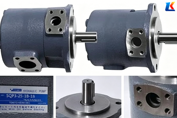
The SQP double vane pump model consists of series code, displacement combination, shaft extension form, installation method and other components. A typical model is taken as an example below:
|
Model Section
|
Description
|
Example
|
|
SQP(S)
|
Basic series code; S indicates low-noise type
|
SQP32
|
|
21/31/32/41/42/43
|
Double pump structure code; the first digit represents the shaft-side pump group, and the second represents the cover-side pump group
|
32 (shaft-side SQP3, cover-side SQP2)
|
|
-XX
|
Shaft-side pump displacement code (unit: mL/r)
|
-21 (displacement: approx. 65.1 mL/r)
|
|
-XX
|
Cover-side pump displacement code
|
-17 (displacement: approx. 52.8 mL/r)
|
|
-XX
|
Shaft extension form (1 = standard type, 86 = reinforced square key)
|
-11
|
|
-XX
|
Mounting flange type
|
-86DC2
|
|
-XX
|
Rotation direction / oil port position
|
-18-T
|
Common displacement and code correspondence: 10 (31.1), 12 (37.3), 14 (43.4), 15 (46.5), 17 (52.8), 19 (59.2), 21 (65.1), 25 (77.8), 30 (93.4), 32 (100), 35 (109), 38 (118), 42 (134) mL/r
2. Five-Step Core Selection Process
1. Clarify Equipment Hydraulic System Requirements (Foundation)
|
Parameter
|
Calculation Method
|
Selection Requirements
|
|
Working Pressure
|
System maximum pressure + 10%-20% safety factor
|
Shall not exceed the pump rated pressure of 17.2MPa; pressure difference between two circuits ≤12MPa (to prevent internal oil leakage)
|
|
Flow Demand
|
Sum of maximum flow of all actuators + 10% margin
|
Total flow of double pump = shaft-side pump flow + cover-side pump flow; Flow = Displacement × Speed × Volumetric Efficiency
|
|
Speed Range
|
Match the driving motor speed
|
Rated speed ≤1800r/min; continuous operation speed is recommended ≤1500r/min
|
|
Working Condition Characteristics
|
Continuous / intermittent operation, impact load / stable load
|
Larger safety factor for continuous working conditions; consider peak pressure for impact working conditions
|
|
Circuit Design
|
High-low pressure compound / dual-circuit independent / confluence control
|
Adopt the configuration of “large displacement low pressure + small displacement high pressure” for high-low pressure compound circuits
|
2. Determine Double Pump Displacement Combination (Key)
-
High-Low Pressure Compound Circuit: High-flow low-pressure pump (shaft side) for fast forward/retraction; small-flow high-pressure pump (cover side) for working feed, e.g., SQP32-32-17
-
Dual-Circuit Independent Control: Select appropriate displacement combination according to the flow demand of the two independent circuits respectively, e.g., SQP41-25-21
-
Confluence Control Circuit: The total flow shall meet the maximum demand of actuators, e.g., SQP31-30-30
Displacement Calculation Formula: q = Qmax / (n × ηv), where Qmax = maximum flow, n = rated speed, ηv = volumetric efficiency (0.85-0.95)
3. Match Installation and Interface Parameters
|
Parameter
|
Selection Key Points
|
|
Installation Method
|
Flange type (ISO/SAE B), shaft extension form (standard / reinforced square key), rotation direction (clockwise / counterclockwise)
|
|
Oil Port Position
|
Discharge port position of shaft-side/cover-side pump (viewed from the pump cover side), which shall match the system pipeline
|
|
Connection Dimension
|
Inlet and outlet thread specifications and flange dimensions to ensure compatibility with system interfaces
|
|
Installation Space
|
Verify the matching of pump body dimensions and equipment installation position, and reserve maintenance space
|
4. Confirm Hydraulic Oil and Environmental Conditions
-
Hydraulic Oil Type: Mineral oil is recommended; viscosity range: 15-40cSt (optimal 22-32cSt); oil temperature range: 10-60℃
-
Oil Cleanliness: Must meet NAS 6 grade (filtration accuracy ≤5μm); replace filter elements regularly
-
Ambient Temperature: Select hydraulic oil with appropriate viscosity grade according to ambient temperature; preheat equipment in low-temperature environments
-
Noise Requirements: Adopt SQPS low-noise series or install silencing devices for noise-sensitive scenarios
5. Verify and Optimize Selection Scheme
-
Power Matching: Calculate the required driving power via P= (p1×Q1 + p2×Q2) / (60×η) to ensure sufficient motor power
-
Thermal Balance Verification: Balance system heat generation and heat dissipation to avoid excessive oil temperature affecting pump service life
-
Economic Evaluation: Comprehensively consider initial cost, operation energy consumption and maintenance cost to select the most cost-effective scheme
-
Alternative Scheme: Prepare 1-2 alternative models to cope with working condition changes or supply shortages
3. Common Selection Mistakes and Avoidance Guidelines
|
Mistake
|
Consequence
|
Correct Practice
|
|
Only check total flow without single pump pressure
|
Overload of one circuit and underpressure of the other
|
Match the pressure of the two circuits separately to ensure all within the rated range
|
|
Ignoring pressure difference limit
|
Internal oil leakage of double pump and reduced efficiency
|
Control the pressure difference between two circuits ≤12MPa; adopt independent single pumps if exceeded
|
|
Substandard oil cleanliness
|
Rapid wear of vanes, stator and valve plate
|
Install 5μm high-precision filter and test oil cleanliness regularly
|
|
Long-term over-speed operation
|
Insufficient lubrication and greatly shortened pump service life
|
Keep continuous operation speed ≤1500r/min and instantaneous speed ≤1800r/min
|
|
No reserved flow/pressure margin
|
Unstable system operation under fluctuating working conditions
|
Reserve 10%-20% flow margin and ensure pressure safety factor ≥1.1
|
4. Selection Case Demonstration
Hydraulic system requirements of an injection molding machine:
-
Fast forward / retraction: pressure 4MPa, flow 120L/min
-
Injection / pressure holding: pressure 16MPa, flow 30L/min
-
Motor speed: 1450r/min
Selection Steps:
-
Calculate displacement:
-
Fast-moving pump: q1=120/(1450×0.9)×1000≈93.9mL/r → select code 30 (93.4mL/r)
-
Injection pump: q2=30/(1450×0.9)×1000≈23.5mL/r → select code 17 (52.8mL/r, meeting pressure holding requirements)
-
-
Series selection: SQP32 series is selected for high-pressure working conditions (shaft-side SQP3, cover-side SQP2)
-
Final model: SQP32-30-17-11-86DC2-18-T
5. Summary and Next Steps
The core of pump selection is to accurately match system pressure, flow rate, speed and displacement, while paying attention to installation, hydraulic oil, environmental and other details. It is recommended to complete system parameter calculation first, then select the specific model according to the SQP series sample. Consult professional hydraulic engineers or pump manufacturer technical support when necessary to ensure the selected model fully meets equipment requirements.
I can recommend a specific SQP double vane pump model for you according to your equipment parameters (maximum pressure, dual-circuit flow demand, motor speed, mounting flange / shaft extension form).