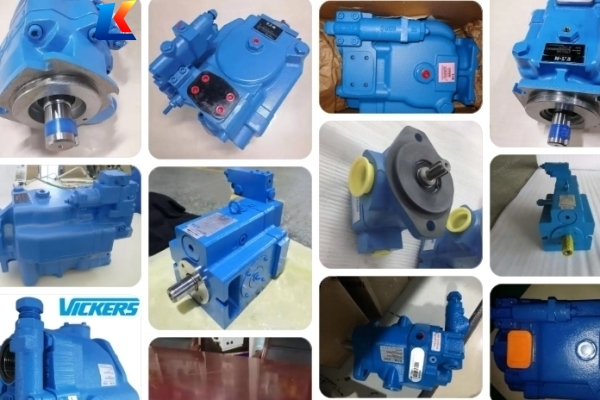
Vickers hydraulic piston Pump PVM series product manual
1. Introduction
The Vickers PVM Series is a line of variable displacement axial piston pumps designed for both industrial and mobile hydraulic applications. Manufactured by Danfoss (formerly Eaton Vickers), these pumps feature a swashplate design, open-circuit configuration, and robust construction, delivering reliable performance with high efficiency and low noise. The PVM Series is engineered to handle a wide range of operating conditions, making it suitable for mining machinery, injection molding equipment, machine tools, and other heavy-duty hydraulic systems.
This manual provides detailed instructions for the safe installation, operation, maintenance, and troubleshooting of Vickers PVM Series pumps. It is essential to read and follow all guidelines contained herein to ensure optimal pump performance, extend service life, and prevent equipment damage or personal injury.
2. Safety Precautions
2.1 General Safety Guidelines
-
Only trained and qualified personnel should install, operate, or maintain the pump. Unauthorized operation may result in serious injury or equipment failure.
-
Before any work is performed on the pump or associated hydraulic system, relieve all system pressure, shut off the power supply, and lock out the power source to prevent accidental startup.
-
Use only Vickers authorized chain links for pump assembly; industry-standard cotter pins on chain links will fail, leading to potential hazards.
-
The PVM hydraulic pumps are marked as equipment for Group II, Category 3 for gas environments, with ignition protection through constructional safety and liquid immersion. The temperature class and maximum surface temperature depend on operating conditions (ambient and fluid temperature) and application duty cycles.
-
Strictly adhere to the maximum operating pressure specified for the pump to avoid damage and potential safety risks.
2.2 Maintenance Safety
-
Thoroughly clean the pump and surrounding area before performing maintenance to prevent dust and contamination, which are detrimental to hydraulic equipment.
-
Use only genuine Vickers replacement parts. Non-genuine parts may not meet performance standards and can void the product warranty.
-
Wear appropriate personal protective equipment (PPE), including safety glasses, gloves, and protective clothing, when handling hydraulic fluids or working on the pump.
3. Specifications & Performance
3.1 Core Specifications
|
Parameter
|
Specification
|
|---|---|
|
Displacement Range
|
18–141 cm³/r (1.1–8.6 in³/r)
|
|
Maximum Operating Pressure
|
315 bar (4570 psi) (upgraded from 280 bar); some models available with 230 bar continuous rating
|
|
Design Type
|
Open-circuit, axial piston, swashplate design
|
|
Input Rotation
|
Clockwise (right hand) or counter-clockwise (left hand)可选
|
|
Fluid Compatibility
|
Petroleum-based, synthetic hydraulic fluids, high-water-content fluids, and phosphate ester fluids
|
|
Noise Level
|
Low noise operation, exceeding modern industrial requirements with a unique three-piece envelope (flange, housing, valve block) and bimetal timing plate to reduce fluid-borne and structure-borne noise
|
3.2 Key Models
The PVM Series includes the following models, covering various displacement requirements: PVM018, PVM020, PVM045, PVM050, PVM057, PVM063, PVM074, PVM081, PVM098, PVM106, PVM131, PVM141.
3.3 Control Options
-
Pressure Compensator (PC): Available for 10–50 cc and 57–141 cc models, maintaining consistent pressure in the hydraulic system.
-
Load Sense (LS): Suitable for 18–45 cc and 57–141 cc models, optimizing flow based on system demand to improve efficiency.
-
Power Control / Torque Limiter: Prevents overloading and reduces energy consumption by limiting torque output.
-
Remote Control: Allows for convenient adjustment of pump parameters from a remote location.
-
Electric Proportional Control (SP/SM): Enables precise, automated control of displacement and pressure.
4. Installation
4.1 Pump Unit Installation
-
Select a mounting location that is clean, dry, and well-ventilated, with sufficient space for maintenance and access to gauge ports and control components.
-
Ensure the mounting surface is flat and rigid to minimize vibration. Use the appropriate mounting flange (SAE configurations available) and fasteners to secure the pump firmly.
-
Align the pump shaft with the drive motor shaft accurately. Misalignment can cause excessive wear, noise, and premature failure. Use a coupling that accommodates minor misalignment and absorbs vibration.
-
Verify the input rotation direction matches the pump’s specified rotation (clockwise or counter-clockwise) to ensure proper operation.
4.2 Pipeline Installation
-
Use clean, debris-free hydraulic lines that are compatible with the operating pressure and fluid type. Ensure lines are properly sized to minimize pressure drop.
-
Install inlet and outlet lines securely, using appropriate fittings. Avoid sharp bends and excessive length in inlet lines to prevent cavitation.
-
Side-ported models are available to facilitate plumbing and fit tight installation spaces. Multiple drain ports allow for various mounting orientations, reducing installation costs.
-
Install a filter in the inlet line to prevent contamination. The filter should have a suitable micron rating (recommended 10–25 μm) to protect the pump’s internal components.
4.3 Hydraulic Fluid Preparation
Fill the hydraulic system with the recommended fluid, ensuring the fluid level is within the specified range. Bleed all air from the system to prevent cavitation and air locks. Check the fluid temperature; the optimal operating temperature range is 40–80°C (104–176°F).
5. Operation
5.1 Pre-Startup Check
-
Inspect the pump for any signs of damage, loose fasteners, or fluid leaks.
-
Verify that the hydraulic fluid level is correct and the fluid is clean.
-
Check all control settings (pressure, flow) to ensure they match the system requirements.
-
Ensure the power supply is connected correctly and the emergency stop is functional.
5.2 Startup Procedure
-
Start the drive motor and run it at low speed (500–1000 rpm) for 2–3 minutes to allow the fluid to circulate and lubricate the pump components.
-
Monitor the pump for unusual noise, vibration, or leaks. If any abnormalities are detected, shut down the system immediately and investigate the cause.
-
Gradually increase the motor speed to the operating speed and adjust the control settings to achieve the desired pressure and flow.
-
Check the fluid temperature and pressure regularly during initial operation to ensure they remain within the specified limits.
5.3 Normal Operation Guidelines
-
Avoid operating the pump beyond the maximum pressure or temperature limits, as this can cause premature wear and component failure.
-
Monitor the fluid condition regularly. Contaminated fluid is a major cause of pump damage; replace the fluid and filter according to the maintenance schedule.
-
Use the adjustable maximum stop to tune the flow to the system’s needs, and utilize gauge ports to monitor inlet and outlet conditions.
6. Maintenance & Service
6.1 Routine Maintenance Schedule
|
Maintenance Task
|
Frequency
|
Details
|
|---|---|---|
|
Fluid Check
|
Daily
|
Check fluid level and condition; top up if necessary.
|
|
Filter Replacement
|
Every 250–500 operating hours
|
Replace inlet and return filters; clean filter housing.
|
|
Fluid Change
|
Every 1000–2000 operating hours
|
Drain old fluid, flush the system, and refill with fresh fluid.
|
|
Visual Inspection
|
Weekly
|
Check for leaks, loose fasteners, and abnormal wear.
|
|
Seal Inspection/Replacement
|
Every 2000 operating hours
|
Inspect shaft seals and O-rings; replace if worn or leaking.
|
6.2 Disassembly & Assembly Guidelines
Simple maintenance can only be performed after the pump has been removed from the machine. Follow these guidelines for disassembly and assembly of key components:
-
Pressure Compensator (18–50 cc): Disassemble by removing the retaining screws, separating the compensator from the pump housing, and inspecting internal components for wear. Reassemble in reverse order, ensuring all parts are clean and properly lubricated.
-
Pressure Compensator (57–141 cc): Follow similar disassembly/assembly steps, noting differences in component size and configuration.
-
Shaft Seal: Replace the shaft seal by removing the pump flange, extracting the old seal, and installing a new seal using the appropriate tool to avoid damage.
-
Torque Controller/Power Limiter (57–141 cc): Disassemble carefully, inspect for worn parts, and reassemble to manufacturer specifications to ensure proper torque limiting function.
7. Troubleshooting
|
Problem
|
Possible Causes
|
Solutions
|
|---|---|---|
|
Low Flow/Pressure
|
1. Contaminated filter; 2. Air in system; 3. Incorrect control settings; 4. Worn pump components
|
1. Replace filter; 2. Bleed air from system; 3. Adjust control settings; 4. Inspect and replace worn components
|
|
Excessive Noise
|
1. Cavitation (inlet restriction); 2. Misalignment; 3. Worn bearings; 4. Fluid contamination
|
1. Check inlet line and filter; 2. Realign pump and motor; 3. Replace bearings; 4. Change fluid and filter
|
|
Fluid Leaks
|
1. Loose fittings; 2. Worn seals/O-rings; 3. Damaged housing
|
1. Tighten fittings; 2. Replace seals/O-rings; 3. Inspect housing and repair/replace if necessary
|
|
Overheating
|
1. Low fluid level; 2. Contaminated fluid; 3. Inadequate cooling; 4. Excessive pressure
|
1. Top up fluid; 2. Change fluid and filter; 3. Check cooling system; 4. Adjust pressure settings
|


