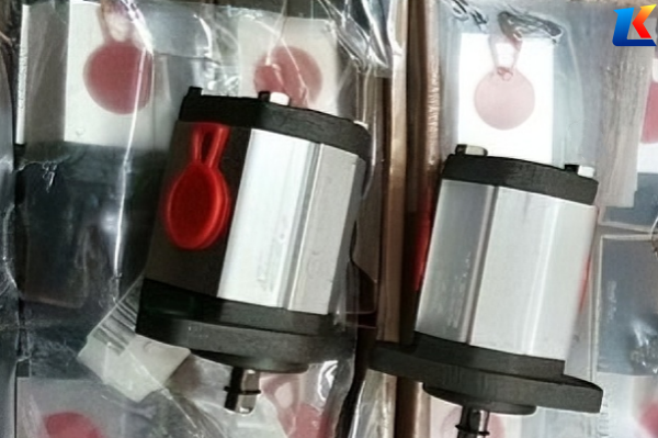
Marzocchi hydraulic pump ALP2A-S-25-FG detailed parameters
1. Model Nomenclature Explanation
-
ALP: Product series, indicating the standard pressure external gear pump, which is suitable for medium and low pressure industrial hydraulic systems.
-
2A: Size group, representing the specific size classification of the pump, which determines the basic installation dimensions and maximum displacement of the pump.
-
S: Mounting method, standing for shaft extension mounting (different from flange mounting marked with “D”).
-
25: Displacement code, corresponding to the theoretical displacement of the pump (specific value refers to the technical specifications below).
-
FG: Special options, where “F” means equipped with a pressure limiting valve, and “G” means adopting mechanical seal for better sealing performance.
2. Basic Information
|
Item
|
Specification
|
|---|---|
|
Brand
|
Marzocchi (Italy)
|
|
Product Type
|
External Gear Pump
|
|
Series
|
ALP Series (Standard Pressure)
|
|
Net Weight
|
Approx. 2.9-3.0 kg
|
|
Structure
|
Single-stage, compact structure
|
3. Key Technical Specifications
|
Technical Parameter
|
Value
|
Unit
|
|---|---|---|
|
Theoretical Displacement
|
17.9
|
cm³/rev (cc/rev)
|
|
Maximum Continuous Pressure
|
210
|
bar (21 MPa)
|
|
Maximum Intermittent Pressure
|
225
|
bar (22.5 MPa)
|
|
Peak Pressure
|
240
|
bar (24 MPa)
|
|
Maximum Speed
|
3600
|
rpm
|
|
Minimum Speed
|
500
|
rpm
|
|
Flow Rate (at 1500 rpm)
|
25.5-26.8
|
L/min
|
|
Efficiency (at 1000-2000 rpm)
|
93
|
%
|
|
Inlet Pressure
|
0.7-3
|
bar
|
4. Material & Sealing
-
Pump Body & Covers: Aluminum alloy, which ensures light weight and good corrosion resistance, suitable for medium and low pressure working conditions.
-
Gears: Special hardened steel, precision machined to minimize internal clearance, reduce internal leakage and improve transmission efficiency.
-
Sealing: Mechanical seal (marked with “G” in the model), with NBR sealing material as auxiliary, ensuring good sealing performance and preventing oil leakage.
5. Shaft & Mounting Details
-
Shaft Type: Conical shaft with a taper of 1:8, equipped with a 4 mm key for stable power transmission.
-
Shaft Dimensions: Shaft diameter is 14.7 mm, shaft length (including fitting edge) is 40 mm, fitting edge diameter is 36.5 mm; shaft thread size is M12×1.5.
-
Mounting Type: Shaft extension mounting (code “S”); flange type is European standard 4-hole mounting, centering diameter is 36.5 mm.
-
Shaft Load & Torque: Maximum torque is 200 Nm, recommended shaft tightening torque is 50±4 Nm.
6. Port Specifications
-
Inlet Port: 3/4″ BSP (GAS) thread, used for connecting the oil suction pipeline.
-
Outlet Port: 1/2″ BSP (GAS) thread, used for connecting the oil discharge pipeline to supply hydraulic oil to the system.
7. Operating Conditions
-
Hydraulic Oil Viscosity: Allowed range is 6-500 cst, recommended range is 10-100 cst for optimal performance.
-
Operating Temperature: -10°C to +80°C (pump start-up and continuous operation temperature range).
-
Rotation Direction: Counterclockwise (CCW) under standard configuration.
8. Product Features
-
High Efficiency & Stability: Precision-machined gears with minimal clearance reduce internal leakage, ensuring high output efficiency and stable pressure supply.
-
Strong Self-priming Capacity: It can quickly suck hydraulic oil even under low-pressure conditions, adapting to various working environments.
-
Low Noise: Optimized gear meshing design and compact structure effectively reduce operating noise, suitable for noise-sensitive occasions.
-
High Reliability: Equipped with a pressure limiting valve (marked with “F” in the model) for overload protection, which can automatically adjust or cut off the oil circuit in abnormal conditions to protect the pump and hydraulic system.
-
Easy Installation & Maintenance: Compact structure, light weight, and standardized mounting dimensions facilitate installation and daily maintenance.
9. Application Fields
10. Notes
-
The parameters listed above are based on standard configuration; for customized products, parameters may vary slightly, please refer to the official product manual.
-
It is recommended to use hydraulic oil that meets the viscosity requirements to ensure the long-term stable operation of the pump.
-
During installation, please ensure that the mounting torque and shaft connection are correct to avoid equipment failure caused by improper installation.
| ALP1A-D-1.4-FG
ALP1A-D-2-FG ALP1A-D-4-FG ALP1A-D-6-FG ALP1A-D-8-FG ALP1A-D-10-FG ALP1A-D-12-FG ALP1A-D-13.8-FG ALP1A-S-4-FG ALP1A-S-6-FG ALP1A-S-10-FG ALP1A-F-8-EP ALP1A-D-5-FG |
ALP2A-D-25-FG
ALP2A-D-30-FG ALP2A-D-34-FG ALP2A-D-35.2-FG ALP2A-S-6-FG ALP2A-S-10-FG ALP2A-S-16-FG ALP2A-S-25-FG ALP2-D-6-FG ALP2-D-9-FG ALP2-D-10-FG ALP2-D-12-FG ALP2-D-13-FG |
ALP2-EP-D-20
ALP2-MU-D-25 ALP2BK1-D-16 ALP2BK2-D-20 ALP3A-D-20-FG ALP3A-D-25-FG ALP3A-D-30-FG ALP3A-D-35-FG ALP3A-D-40-FG ALP3A-D-50-FG ALP3A-D-60-FG ALP3A-D-70-FG ALP3A-D-80-FG |
ALP3A-D-87-FG
ALP3A-S-30-FG ALP3A-S-50-FG ALP3-FG-KA-D-40 ALP3-MU-D-50 ALP3A-FA-KA-D-60 ALP3A-MU-D-70 ALP3-D-25-FG ALP3-D-45-FG ALP3A-D-32-EP ALP3A-S-65-EP ALP4A-D-87-FG ALP4A-D-100-FG |
ALP4A-D-120-FG
ALP4A-D-140-FG ALP4A-D-160-FG ALP4A-D-180-FG ALP4A-D-200-FG ALP4A-S-100-FG ALP4A-S-120-FG ALP4E-D-150-FG ALP4A-D-90-EP ALP4A-D-110-FG ALP4A-S-140-EP ALP4A-D-170-FG ALP4-MU-D-190-FG |


