Product manual of Vickers vane pump 20V/25V/35V/45V series
1. Introduction
1.1 Product Overview
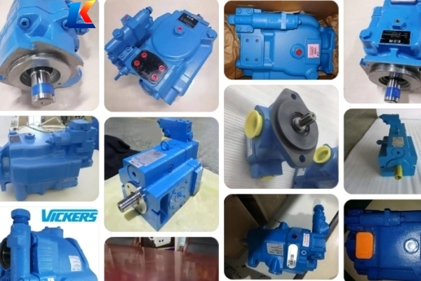
The Vickers 20V, 25V, 35V, and 45V series are fixed displacement, balanced vane pumps belonging to the V-series (Design No. 22). They are engineered for medium-pressure industrial and mobile hydraulic systems, featuring a unique cartridge design, high volumetric efficiency, and ultra-quiet 12-vane operation. These pumps offer exceptional reliability, versatility, and easy maintenance, making them a preferred choice for a wide range of applications. The modular cartridge kit allows for quick replacement without removing the pump from the system, significantly reducing downtime.
1.2 Scope of Application
-
Industrial Machinery: Machine tools, hydraulic presses, plastic injection molding machines, die-casting machines, and conveyor systems.
-
Mobile Equipment: Construction machinery, agricultural tractors, forklifts, material handling equipment, and utility vehicles.
-
Marine & Other: Marine hydraulic systems, test benches, hydraulic power units, and various industrial automation equipment.
1.3 Safety Precautions
-
All personnel must read and understand this manual thoroughly before installation, operation, or maintenance.
-
Isolate the power supply and relieve all system pressure before any disassembly or maintenance to prevent injury or equipment damage.
-
Do not operate the pump beyond the rated maximum pressure, speed, or temperature limits to avoid failure, leaks, or hazards.
-
Use only recommended hydraulic fluids and maintain fluid cleanliness to prevent premature wear and component blockage.
-
Wear appropriate personal protective equipment (PPE) such as safety glasses and gloves when working on the system.
2. Technical Specifications
2.1 General Technical Parameters
-
Inlet Pressure: Recommended 0 to 0.34 bar (0 to 5 psi) gauge; maximum 1.38 bar (20 psi); inlet vacuum not to exceed 0.17 bar (5 in Hg).
-
Fluid Compatibility: Mineral oil, anti-wear hydraulic oil, water-glycol fluids (F2), and phosphate ester fluids (F3).
-
Fluid Viscosity: 13 to 860 cSt (operating); optimal 16 to 60 cSt.
-
Operating Temperature: -17°C to 82°C (0°F to 180°F).
-
Shaft Rotation: Clockwise (R) or Counterclockwise (L) (viewed from shaft end).
-
Port Orientation: 4-position adjustable (A, B, C, D) for flexible installation.
2.2 Detailed Model Specifications
2.2.1 20V Series Single Vane Pump
|
Model Code
|
Geometric Displacement (cm³/r / in³/r)
|
Max Continuous Pressure (bar / psi)
|
Max Speed (rpm)
|
Flow @ 1800 rpm (L/min / USgpm)
|
Min Speed (rpm)
|
Weight (kg / lbs)
|
|
20V-2
|
7.5 / 0.46
|
207 / 3000
|
3600
|
13.5 / 3.6
|
600
|
12.0 / 26.0
|
|
20V-3
|
10.0 / 0.61
|
207 / 3000
|
3600
|
18.0 / 4.8
|
600
|
12.0 / 26.0
|
|
20V-4
|
13.0 / 0.79
|
207 / 3000
|
3600
|
23.4 / 6.2
|
600
|
12.0 / 26.0
|
|
20V-5
|
16.5 / 1.01
|
207 / 3000
|
3600
|
29.7 / 7.8
|
600
|
12.0 / 26.0
|
|
20V-6
|
19.0 / 1.16
|
207 / 3000
|
3600
|
34.2 / 9.0
|
600
|
12.0 / 26.0
|
|
20V-7
|
23.0 / 1.40
|
207 / 3000
|
3600
|
41.4 / 10.9
|
600
|
12.0 / 26.0
|
|
20V-8
|
26.0 / 1.59
|
207 / 3000
|
3600
|
46.8 / 12.4
|
600
|
12.0 / 26.0
|
|
20V-9
|
29.0 / 1.77
|
207 / 3000
|
3600
|
52.2 / 13.8
|
600
|
12.0 / 26.0
|
|
20V-10
|
32.0 / 1.95
|
207 / 3000
|
3600
|
57.6 / 15.2
|
600
|
12.0 / 26.0
|
|
20V-11
|
35.0 / 2.14
|
207 / 3000
|
3600
|
63.0 / 16.6
|
600
|
12.0 / 26.0
|
|
20V-12
|
38.0 / 2.32
|
207 / 3000
|
3600
|
68.4 / 18.1
|
600
|
12.0 / 26.0
|
|
20V-14
|
45.0 / 2.75
|
207 / 3000
|
3600
|
81.0 / 21.4
|
600
|
12.0 / 26.0
|
2.2.2 25V Series Single Vane Pump
|
Model Code
|
Geometric Displacement (cm³/r / in³/r)
|
Max Continuous Pressure (bar / psi)
|
Max Speed (rpm)
|
Flow @ 1800 rpm (L/min / USgpm)
|
Min Speed (rpm)
|
Weight (kg / lbs)
|
|
25V-10
|
33.0 / 2.02
|
172 / 2500
|
3600
|
59.4 / 15.7
|
600
|
14.8 / 33.0
|
|
25V-12
|
39.0 / 2.38
|
172 / 2500
|
3600
|
70.2 / 18.5
|
600
|
14.8 / 33.0
|
|
25V-14
|
45.0 / 2.75
|
172 / 2500
|
3600
|
81.0 / 21.4
|
600
|
14.8 / 33.0
|
|
25V-17
|
56.0 / 3.42
|
172 / 2500
|
3600
|
100.8 / 26.6
|
600
|
14.8 / 33.0
|
|
25V-19
|
61.0 / 3.72
|
172 / 2500
|
3600
|
109.8 / 29.0
|
600
|
14.8 / 33.0
|
|
25V-21
|
67.0 / 4.09
|
172 / 2500
|
3600
|
120.6 / 31.9
|
600
|
14.8 / 33.0
|
2.2.3 35V Series Single Vane Pump
|
Model Code
|
Geometric Displacement (cm³/r / in³/r)
|
Max Continuous Pressure (bar / psi)
|
Max Speed (rpm)
|
Flow @ 1800 rpm (L/min / USgpm)
|
Min Speed (rpm)
|
Weight (kg / lbs)
|
|
35V-21
|
81.0 / 4.94
|
172 / 2500
|
3000
|
145.8 / 38.5
|
600
|
22.0 / 48.5
|
|
35V-25
|
98.0 / 5.98
|
172 / 2500
|
3000
|
176.4 / 46.6
|
600
|
22.0 / 48.5
|
|
35V-30
|
118.0 / 7.20
|
172 / 2500
|
3000
|
212.4 / 56.1
|
600
|
22.0 / 48.5
|
|
35V-32
|
126.0 / 7.69
|
172 / 2500
|
3000
|
226.8 / 59.9
|
600
|
22.0 / 48.5
|
|
35V-35
|
138.0 / 8.42
|
172 / 2500
|
3000
|
248.4 / 65.6
|
600
|
22.0 / 48.5
|
|
35V-38
|
149.0 / 9.09
|
172 / 2500
|
3000
|
268.2 / 70.8
|
600
|
22.0 / 48.5
|
|
35V-45
|
177.0 / 10.80
|
172 / 2500
|
3000
|
318.6 / 84.2
|
600
|
22.0 / 48.5
|
2.2.4 45V Series Single Vane Pump
|
Model Code
|
Geometric Displacement (cm³/r / in³/r)
|
Max Continuous Pressure (bar / psi)
|
Max Speed (rpm)
|
Flow @ 1800 rpm (L/min / USgpm)
|
Min Speed (rpm)
|
Weight (kg / lbs)
|
|
45V-42
|
169.0 / 10.31
|
140 / 2000
|
2800
|
304.2 / 80.3
|
600
|
34.0 / 75.0
|
|
45V-45
|
181.0 / 11.04
|
140 / 2000
|
2800
|
325.8 / 86.1
|
600
|
34.0 / 75.0
|
|
45V-50
|
202.0 / 12.32
|
140 / 2000
|
2800
|
363.6 / 96.0
|
600
|
34.0 / 75.0
|
|
45V-57
|
228.0 / 13.91
|
140 / 2000
|
2800
|
410.4 / 108.4
|
600
|
34.0 / 75.0
|
|
45V-60
|
241.0 / 14.71
|
140 / 2000
|
2800
|
433.8 / 114.6
|
600
|
34.0 / 75.0
|
|
45V-66
|
264.0 / 16.11
|
140 / 2000
|
2800
|
475.2 / 125.5
|
600
|
34.0 / 75.0
|
|
45V-75
|
299.0 / 18.25
|
140 / 2000
|
2800
|
538.2 / 142.2
|
600
|
34.0 / 75.0
|
3. Installation Instructions
3.1 Mounting
-
The pump can be flange-mounted (standard) or foot-mounted (F-option). The mounting surface must be rigid and flat to prevent housing distortion.
-
Align the pump shaft with the drive shaft using a flexible coupling. Maximum misalignment: 0.1 mm radial, 0.05 mm axial, 1° angular.
-
Tighten mounting bolts to the recommended torque: M8 (18-22 N·m), M10 (35-40 N·m), M12 (60-65 N·m).
3.2 Plumbing
-
Inlet Line: Use a short, large-diameter, smooth-bore hose. Avoid elbows and restrictions. Ensure no air leaks.
-
Outlet Line: Install a high-pressure hose or pipe with a pressure relief valve.
-
Drain Line: Direct the case drain line back to the tank separately. Do not route it through a filter or valve.
3.3 Priming & Filling
-
Fill the pump and inlet line with clean hydraulic fluid before startup.
-
Rotate the shaft manually by hand to bleed air from the cartridge.
-
Maintain proper oil level in the reservoir to prevent air ingestion.
4. Operation Guidelines
4.1 Startup
-
Start the pump at low speed (≈600 rpm) with the system unloaded for 5-10 minutes to circulate fluid and purge air.
-
Check for leaks, unusual noise, or vibration.
-
Gradually increase speed and load to operating conditions.
4.2 Normal Operation
-
Operate within the specified pressure and speed ranges.
-
Monitor fluid temperature (max 82°C) and condition.
-
Avoid prolonged operation at maximum pressure and low speed.
4.3 Shutdown
-
Reduce speed and unload the system before stopping.
-
For extended shutdowns, protect the pump from contamination and corrosion.
5. Maintenance & Troubleshooting
5.1 Maintenance Schedule
-
Daily: Check fluid level and for leaks.
-
Weekly: Inspect fluid condition; check for abnormal noise/vibration.
-
Every 250 hrs: Change or clean inlet filter.
-
Every 1000 hrs: Change hydraulic fluid and all filters.
-
Every 2000 hrs: Inspect shaft seal and bearings.
5.2 Common Troubleshooting
|
Symptom
|
Possible Cause
|
Solution
|
|
Insufficient Flow/Pressure
|
1. Air in inlet line 2. Worn cartridge 3. Clogged filter 4. Leaking seals
|
1. Fix leaks, prime pump 2. Replace cartridge kit 3. Clean/replace filter 4. Replace seals
|
|
Excessive Noise/Vibration
|
1. Cavitation (air ingestion) 2. Misalignment 3. Worn bearings 4. Restricted inlet
|
1. Check inlet line, fluid level 2. Correct alignment 3. Replace bearings 4. Improve inlet plumbing
|
|
Overheating
|
1. High pressure/load 2. Insufficient cooling 3. Wrong fluid viscosity
|
1. Reduce load 2. Check cooler 3. Use correct viscosity oil
|
|
External Leakage
|
1. Loose connections 2. Worn shaft seal 3. Cracked housing
|
1. Tighten fittings 2. Replace shaft seal 3. Replace pump
|
5.3 Cartridge Replacement
The V-series design allows for easy cartridge replacement:
-
Relieve pressure and disconnect hoses.
-
Remove the end cover bolts.
-
Extract the old cartridge.
-
Insert new cartridge, aligning keyways.
-
Reassemble and prime.
6. Storage & Handling
-
Store in a clean, dry environment.
-
Fill with preservative oil and seal ports if stored for over 3 months.
-
Protect shafts and threads from damage.
7. Warranty
Vickers 20V/25V/35V/45V series pumps are warranted against defects in material and workmanship for 12 months from installation or 18 months from shipment, whichever comes first. Warranty is void if damage results from misuse, improper installation, lack of maintenance, or use of non-genuine parts.
8. Appendix
8.1 Model Nomenclature Example
20V – 5 – A – 1 – R – 22
-
20V: Series & Size
-
5: Displacement Code
-
A: Port Orientation
-
1: Shaft Type
-
R: Rotation
-
22: Design Number
8.2 Technical Support
For service, parts, or further information, contact your local Eaton-Vickers authorized distributor. Provide the full model number for accurate assistance.


