Vickers single vane pump 20V/25V series
1. Series Overview
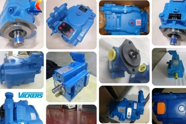
Vickers 20V and 25V series are high-performance single vane pumps designed for medium-pressure industrial applications, such as plastic injection machinery, tool machinery, die casting machinery, and metallurgy equipment. Featuring a hydraulic balancing structure and a 12-vane system, these pumps offer stable performance, low noise, long service life, and easy maintenance due to the independent cartridge design that allows servicing without removing the pump from its mounting. They are available in various displacements and configurations to meet diverse hydraulic system requirements.
2. Model Naming Rules
The model code of Vickers 20V/25V series single vane pumps follows a standardized format, with each segment indicating specific configurations. The general structure is as follows (suffixes may vary based on actual requirements):
(F3) – [Series Designation] – [Displacement Code] – [Pilot Designation] – [Port Connection] – [Mounting Type] – [Shaft Type] – [Outlet Position] – [Rotation Direction] – [Special Suffix]
Key explanations of each segment:
-
F3: Optional Viton seals (omit if not required).
-
Series Designation: 20V or 25V, indicating the pump frame size.
-
Displacement Code: Numerical value representing the geometric displacement (unit: cm³/r), e.g., 7, 10, 12, 14, etc..
-
Pilot Designation: Omit for standard pilot; S for SAE pilot (per ISO 3019/1); M for metric pilot (per ISO 3019/2, not applicable for 20V series).
-
Port Connection: A for SAE 4-bolt flange; M for metric 4-bolt flange (not applicable for 20V series).
-
Mounting Type: Omit for flange mounting; F for foot mounting.
-
Shaft Type: Standard pilot shafts, with options of straight key, spline, etc. (20V series has limited spline options).
-
Outlet Position: Viewed from the cover end of the pump; A (opposite inlet), B (90° CCW from inlet), C (inline with inlet), D (90° CW from inlet).
-
Rotation Direction: Viewed from the shaft end; L for left-hand (counterclockwise), omit for right-hand (clockwise).
-
Special Suffix: e.g., 167 for 2-bolt, 5.00” dia. pilot (only for 25V series, not applicable for VS/VM models).
Example: 20V14A – 20V series, 45 cm³/r (2.78 in³/r) displacement, SAE 4-bolt flange port, standard flange mounting, right-hand rotation, no special suffix.
3. Technical Parameters
The following parameters are standard specifications for 20V/25V series single vane pumps (subject to change based on fluid type and operating conditions). All units comply with international industrial standards.
3.1 20V Series Parameters
|
Model
|
Geometric Displacement
|
Max Operating Pressure (bar/psi)
|
Rated Speed (rpm)
|
Max Speed (rpm)
|
Min Speed (rpm)
|
|---|---|---|---|---|---|
|
20V2
|
7.5 cm³/r (0.46 in³/r)
|
13.8/2000
|
1200
|
1800
|
600
|
|
20V5
|
16.5 cm³/r (1.01 in³/r)
|
20.7/3000
|
1200
|
1800
|
600
|
|
20V8
|
27 cm³/r (1.67 in³/r)
|
20.7/3000
|
1200
|
1800
|
600
|
|
20V11
|
36 cm³/r (2.20 in³/r)
|
20.7/3000
|
1200
|
1800
|
600
|
|
20V14
|
45 cm³/r (2.78 in³/r)
|
13.8/2000
|
1200
|
1800
|
600
|
Note: For 20V series, the max operating pressure varies with displacement; larger displacement models have slightly lower pressure ratings. When using water-glycol fluid or water-in-oil emulsions, the max pressure and speed will be reduced accordingly.
3.2 25V Series Parameters
|
Model
|
Geometric Displacement
|
Max Operating Pressure (bar/psi)
|
Rated Speed (rpm)
|
Max Speed (rpm)
|
Min Speed (rpm)
|
|---|---|---|---|---|---|
|
25V10
|
32.5 cm³/r (1.98 in³/r)
|
17.2/2500
|
1200
|
1800
|
600
|
|
25V12
|
39 cm³/r (2.38 in³/r)
|
17.2/2500
|
1200
|
1800
|
600
|
|
25V14
|
45 cm³/r (2.78 in³/r)
|
17.2/2500
|
1200
|
1800
|
600
|
|
25V17
|
55 cm³/r (3.36 in³/r)
|
17.2/2500
|
1200
|
1800
|
600
|
|
25V21
|
67 cm³/r (4.13 in³/r)
|
17.2/2500
|
1200
|
1800
|
600
|
|
25V25
|
81 cm³/r (4.94 in³/r)
|
13.8/2000
|
1200
|
1800
|
600
|
Note: The 25V series supports SAE and metric pilot shafts, with more shaft type options than the 20V series. For models using phosphate ester fluid, please specify the F3 suffix for Viton seals.
4. Key Features
-
Hydraulic balancing structure reduces vane pressure on the stator, ensuring stable performance and extended service life.
-
12-vane system minimizes flow pulsation, achieving low noise operation, which is ideal for indoor industrial environments.
-
Independent cartridge design allows easy maintenance without disassembling the pump from the mounting bracket.
-
Wide displacement range and multiple configurations (port positions, shaft types, mounting types) to adapt to different application scenarios.
-
High volumetric efficiency (>90%), reducing energy loss and improving system efficiency.
-
Compatible with anti-wear hydraulic oil, phosphate ester fluid, water-glycol fluid, and water-in-oil emulsions (parameters vary by fluid type).
5. Application Notes
-
The recommended fluid cleanliness level is ISO 18/15 to ensure the pump’s service life.
-
Before installation, apply a small amount of system fluid to the inner circumference of the shaft seal, and install the seal with the spring facing the bearing.
-
Operating parameters (pressure, speed) should not exceed the specified limits to avoid damage to the pump.
-
When ordering spare parts, specify the complete model code to ensure compatibility, especially for left-hand rotation models (add suffix “L” to the kit number).


