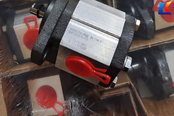
Marzocchi hydraulic pump GHP3A-D-75-FG, GHP3A-D-87-FG
1. Introduction
This manual provides detailed instructions for the correct installation, operation, maintenance, and troubleshooting of the Marzocchi GHP3A-D-75-FG and GHP3A-D-87-FG hydraulic gear pumps. These pumps belong to the GHP3A series, which is designed for high-pressure hydraulic applications, featuring high volumetric efficiency, low noise, strong vibration resistance, and easy maintenance. Strictly following the guidelines in this manual will ensure the pump’s long-term stable operation and optimal performance, and help avoid equipment damage or personal injury caused by improper operation.
The GHP3A-D-75-FG and GHP3A-D-87-FG are external gear fixed-displacement hydraulic pumps, integrated with a pressure relief valve and G-type mechanical seal, widely applicable to construction machinery, industrial equipment, and hydraulic systems requiring stable medium-high pressure power supply.
2. Model Interpretation
The model codes of GHP3A-D-75-FG and GHP3A-D-87-FG have specific meanings, which help to quickly identify product specifications and configurations:
-
GHP: Series identification, indicating a high-pressure external gear fixed-displacement hydraulic pump, a classic high-pressure pump series of Marzocchi, suitable for medium-high pressure hydraulic systems.
-
3A: Size specification code, representing the 3A model, which determines the basic installation dimensions, overall dimensions, and displacement range of the pump, and is one of the core parameters for product selection.
-
D: Rotation direction identification, indicating clockwise rotation (observed from the shaft end, the gear rotates clockwise); the corresponding counterclockwise rotation model is marked with “S”.
-
75/87: Theoretical displacement identification, indicating that the theoretical displacement of the pump is 75 cm³/rev (for GHP3A-D-75-FG) and 87 cm³/rev (for GHP3A-D-87-FG), i.e., the theoretical volume of hydraulic oil output by the gear per revolution.
-
FG: Function option combination, where “F” stands for built-in pressure relief valve (safety valve), which can adjust the opening pressure according to system requirements to protect the pump body and pipeline safety; “G” stands for G-type mechanical seal, which has good sealing performance and temperature resistance to achieve zero-leakage operation.
3. Technical Specifications
The following are the key technical parameters of GHP3A-D-75-FG and GHP3A-D-87-FG hydraulic pumps, based on standard working conditions (ambient temperature: 20±5℃, hydraulic oil viscosity: 40 cSt):
|
Parameter Name
|
GHP3A-D-75-FG
|
GHP3A-D-87-FG
|
Remarks
|
|---|---|---|---|
|
Theoretical Displacement
|
75 cm³/rev
|
87 cm³/rev
|
Core parameter determining output flow
|
|
Maximum Continuous Pressure
|
280 bar
|
280 bar
|
Long-term stable working pressure
|
|
Maximum Intermittent Pressure
|
295 bar
|
295 bar
|
Continuous working time ≤ 10% of total working time
|
|
Peak Pressure
|
310 bar
|
310 bar
|
Instantaneous pressure, not allowed to last
|
|
Maximum Rotational Speed
|
3000 rpm
|
2800 rpm
|
No-load speed, avoid exceeding for a long time
|
|
Minimum Rotational Speed
|
500 rpm
|
500 rpm
|
Ensure sufficient lubrication and suction
|
|
Recommended Hydraulic Oil
|
ISO VG 46 hydraulic oil
|
ISO VG 46 hydraulic oil
|
Viscosity range: 10-100 cSt
|
|
Working Temperature Range
|
-20℃ ~ +80℃
|
-20℃ ~ +80℃
|
Exceeding the range will damage seals and components
|
|
Seal Type
|
G-type mechanical seal
|
G-type mechanical seal
|
Zero-leakage design, suitable for most hydraulic media
|
|
Built-in Component
|
Pressure relief valve
|
Pressure relief valve
|
Adjustable opening pressure
|
Note: The parameters above are standard values. For special working conditions (such as high temperature, low temperature, or special media), please contact Marzocchi’s after-sales service for customized solutions. The GHP3A series pumps are made of cast iron and aluminum, ensuring good structural strength and corrosion resistance.
4. Installation Instructions
4.1 Installation Preparation
-
Check the pump model and specifications to ensure they match the system requirements. Inspect the pump for damage, oil leakage, or loose components caused by transportation.
-
Prepare installation tools (wrenches, screwdrivers, etc.), sealing gaskets, and hydraulic oil that meets the specifications. Ensure the installation site is clean, dry, and well-ventilated, avoiding direct sunlight and high-temperature environments.
-
Check the cleanliness of the hydraulic system pipeline. The pipeline should be cleaned to remove impurities (such as metal chips, dust, and oil sludge) to prevent wear of the pump’s internal components and blockage of the pressure relief valve.
4.2 Installation Steps
-
Mount the pump on the motor or bracket using bolts that meet the specifications. Ensure the pump’s shaft is coaxial with the motor’s shaft; the coaxiality error should not exceed 0.1 mm. Avoid excessive tightening of the bolts to prevent deformation of the pump body.
-
Connect the inlet and outlet pipelines. The inlet pipeline should be short and straight, with a diameter not smaller than the pump’s inlet port, to reduce suction resistance and avoid cavitation. The outlet pipeline should be equipped with a pressure gauge and a shut-off valve for pressure monitoring and maintenance.
-
Install the sealing gasket between the pump and the pipeline interface to ensure tight sealing and prevent oil leakage. Do not use excessive force when tightening the pipeline joints to avoid damaging the threads.
-
Fill the pump with hydraulic oil through the oil filling port before starting, ensuring the oil level is higher than the pump’s internal gear to achieve sufficient lubrication and avoid dry friction during startup.
-
Check the rotation direction of the pump. The rotation direction should be consistent with the direction marked on the pump body (clockwise for model “D”). Do not reverse the rotation direction, otherwise, it will damage the pump’s internal components and affect the pressure relief valve’s normal operation.
4.3 Installation Notes
-
The pump should be installed in a position that is easy to inspect, maintain, and disassemble, leaving sufficient space around the pump for operation.
-
Avoid installing the pump in a vibrating environment; if necessary, install a shock absorber between the pump and the bracket to reduce vibration and extend the pump’s service life.
-
The inlet pipeline should be equipped with a filter with a filtration accuracy of ≤ 25 μm to prevent impurities from entering the pump and causing wear.
5. Operation Instructions
5.1 Startup Operation
-
Before starting the motor, check the oil level of the hydraulic system, the tightness of the pipeline joints, and the rotation direction of the pump. Ensure all components are in normal condition.
-
Start the motor at low speed (1000-1500 rpm) and run it idly for 5-10 minutes. During idling, check for oil leakage, abnormal noise, or overheating of the pump body. If any abnormality is found, stop the motor immediately for inspection.
-
Gradually increase the motor speed to the rated speed, and adjust the pressure relief valve to the required working pressure according to the system requirements. The pressure adjustment should be gradual, avoiding sudden high pressure which may damage the pump and pipeline.
-
After the pump runs stably for 10-15 minutes, check the oil temperature, pressure, and flow rate to ensure they are within the standard range. The normal oil temperature should be 30℃ ~ 60℃; if the oil temperature exceeds 70℃, stop the pump to cool down and check the cause.
5.2 Normal Operation
-
During operation, regularly monitor the pressure gauge and oil temperature gauge to ensure the pump operates under the rated pressure and temperature. Do not exceed the maximum continuous pressure for a long time.
-
Avoid sudden start and stop of the pump; when stopping the pump, first reduce the system pressure to zero, then stop the motor to avoid impact on the pump and hydraulic system.
-
If the pump is not used for a long time (more than 1 month), drain the hydraulic oil in the pump and pipeline, clean the pump and pipeline, and fill it with new hydraulic oil before restarting.
5.3 Emergency Shutdown
Stop the motor immediately in the following situations, and troubleshoot after the pump cools down:
-
The oil temperature exceeds 80℃, and the cooling system fails to reduce the temperature.
-
Severe oil leakage occurs at the pump body or pipeline joints.
-
Abnormal noise (such as sharp friction sound, impact sound) or vibration occurs during operation.
-
The pressure gauge shows abnormal pressure (exceeding the peak pressure or no pressure).
6. Maintenance and Maintenance
6.1 Daily Maintenance (Daily)
-
Check the oil level of the hydraulic system, and add hydraulic oil that meets the specifications in time if the oil level is too low. Ensure the hydraulic oil is free of impurities, turbidity, or discoloration; if so, replace the hydraulic oil immediately.
-
Inspect the pump body, pipeline joints, and seals for oil leakage. Replace the damaged seals or gaskets in time.
-
Clean the surface of the pump and the surrounding area to avoid dust and impurities accumulating on the pump body, which may affect heat dissipation.
6.2 Regular Maintenance (Monthly)
-
Check the filter of the inlet pipeline, clean or replace the filter element if it is clogged to ensure smooth suction of the pump.
-
Inspect the tightness of the pump’s fixing bolts and pipeline joints, and tighten them if they are loose.
-
Check the operation of the pressure relief valve, adjust the opening pressure if necessary, and ensure it can work normally.
-
Measure the oil viscosity and cleanliness of the hydraulic oil; if it does not meet the requirements, replace the hydraulic oil and clean the oil tank.
6.3 Annual Maintenance (Yearly)
-
Disassemble the pump, clean the internal components (gears, bushings, pressure relief valve, etc.), and inspect for wear, deformation, or damage. Replace the worn or damaged components in time.
-
Replace all seals and gaskets to ensure the sealing performance of the pump.
-
Inspect the pump’s shaft and bearing for wear, and replace the bearing if necessary.
-
Reassemble the pump according to the installation steps, fill it with new hydraulic oil, and test run it to ensure the pump operates normally.
6.4 Maintenance Notes
-
Before maintenance, stop the motor, release the system pressure, and wait for the hydraulic oil to cool down to avoid scalding.
-
Use special tools for disassembly and assembly, and avoid damaging the pump’s internal components and threads.
-
The replaced components should be original Marzocchi accessories to ensure compatibility and performance. Do not use inferior accessories, otherwise, it will affect the pump’s service life and safety.
-
After maintenance, record the maintenance content, time, and replaced components for future reference.
7. Troubleshooting
The following are common faults, causes, and solutions of GHP3A-D-75-FG and GHP3A-D-87-FG hydraulic pumps. If the fault cannot be solved, please contact Marzocchi’s after-sales service for professional support.
|
Common Faults
|
Possible Causes
|
Solutions
|
|---|---|---|
|
No pressure output or low pressure
|
1. Hydraulic oil level is too low, insufficient suction; 2. Inlet pipeline is clogged or leaking, causing cavitation; 3. Pressure relief valve is stuck or damaged, unable to build pressure; 4. Internal wear of the pump (gears, bushings), resulting in internal leakage; 5. Rotation direction is reversed.
|
1. Add hydraulic oil to the standard level; 2. Clean the inlet pipeline, repair leaks; 3. Disassemble and clean the pressure relief valve, replace damaged parts; 4. Disassemble the pump, replace worn components; 5. Adjust the motor rotation direction to match the pump’s marked direction.
|
|
Oil leakage at the pump body or pipeline joints
|
1. Seals or gaskets are worn, aged, or damaged; 2. Pipeline joints are loose; 3. Pump body is deformed or cracked; 4. Excessive system pressure.
|
1. Replace worn seals or gaskets; 2. Tighten pipeline joints; 3. Replace the pump body if it is deformed or cracked; 4. Adjust the system pressure to the rated range.
|
|
Abnormal noise during operation
|
1. Insufficient hydraulic oil, cavitation; 2. Impurities in the hydraulic oil, causing wear of internal components; 3. Coaxiality error between the pump and motor is too large; 4. Bearing wear or damage; 5. Loose components.
|
1. Add hydraulic oil, check the inlet pipeline for blockage; 2. Replace hydraulic oil, clean the filter; 3. Adjust the coaxiality between the pump and motor; 4. Replace worn or damaged bearings; 5. Tighten loose components.
|
|
Overheating of the pump body
|
1. Oil temperature is too high; 2. Insufficient lubrication, dry friction between internal components; 3. Excessive system pressure; 4. Blockage of the pump’s internal oil circuit; 5. Poor heat dissipation of the pump body.
|
1. Check the cooling system, cool down the hydraulic oil; 2. Ensure the pump is filled with hydraulic oil, check the oil viscosity; 3. Adjust the system pressure to the rated range; 4. Disassemble and clean the pump’s internal oil circuit; 5. Clean the pump surface, improve ventilation and heat dissipation conditions.
|
|
Unstable flow output
|
1. Fluctuation of motor speed; 2. Internal leakage of the pump; 3. Clogging of the inlet or outlet pipeline; 4. Pressure relief valve works abnormally.
|
1. Stabilize the motor speed; 2. Disassemble the pump, repair internal leakage; 3. Clean the inlet and outlet pipelines; 4. Inspect and adjust the pressure relief valve.
|
8. Safety Precautions
-
Only trained and qualified personnel are allowed to install, operate, and maintain the pump. Before operation, read this manual carefully and master the correct operation methods.
-
Do not operate the pump beyond the rated pressure and speed, otherwise, it will cause damage to the pump and hydraulic system, and may lead to safety accidents.
-
During operation, do not touch the high-temperature pump body and pipeline to avoid scalding. Do not disassemble the pump or pipeline when the system is under pressure to avoid oil injection and injury.
-
The hydraulic oil used must meet the specifications, and it is strictly forbidden to mix different types of hydraulic oil to avoid chemical reactions that damage the pump’s internal components.
-
Regularly inspect the safety components (pressure relief valve, pressure gauge, etc.) to ensure they work normally. If any abnormality is found, stop the operation immediately for inspection and repair.
-
When the pump is out of service for a long time, cut off the power supply, drain the hydraulic oil, and store it in a dry, ventilated place to avoid rust and damage.


