Marzocchi hydraulic gear pump GHP3A-D-70-FG, GHP3A-D-60-FG
1. General Information
1.1 Product Overview
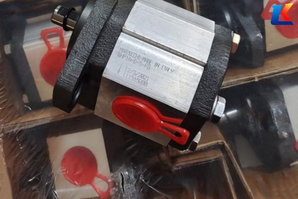
The Marzocchi GHP3A-D-70-FG and GHP3A-D-60-FG are high-performance external hydraulic gear pumps, belonging to the GHP3A series. These pumps are designed to convert mechanical power into hydraulic power, widely used in industrial processes, agricultural applications, heavy plant, and commercial equipment due to their high efficiency, stability, and durability. Both models feature an aluminum body, cast iron flange and cover, and adopt special hardened steel gears to ensure reliable operation under harsh working conditions.
The key difference between the two models lies in their displacement and corresponding flow rate, which are tailored to different hydraulic system requirements. This manual provides detailed instructions for installation, operation, maintenance, and troubleshooting of both models to ensure safe and efficient use.
1.2 Safety Precautions
-
Before installation and operation, read this manual carefully and follow all instructions. Improper operation may cause equipment damage, personal injury, or property loss.
-
Do not operate the pump beyond the specified technical parameters (e.g., maximum pressure, speed, temperature), as this will shorten the pump’s service life and may lead to failure.
-
Ensure the hydraulic system is depressurized and the power supply is cut off before performing any maintenance, disassembly, or inspection.
-
Use only recommended hydraulic oil and maintain proper oil cleanliness to prevent internal component wear.
-
Wear appropriate personal protective equipment (PPE) such as gloves and goggles when operating or maintaining the pump.
-
The pump’s rotation direction must match the motor’s rotation direction; reverse installation will cause abnormal oil suction and discharge, and damage seals and gears.
2. Technical Specifications
|
Specification Item
|
GHP3A-D-60-FG
|
GHP3A-D-70-FG
|
|---|---|---|
|
Pump Type
|
External Gear Pump
|
External Gear Pump
|
|
Series
|
GHP3A
|
GHP3A
|
|
Displacement
|
39 cc/rev
|
71 cc/rev
|
|
Flow Rate at 1500 rpm
|
56 L/min
|
101 L/min
|
|
Rotation Direction
|
Clockwise (CW, viewed from the shaft end; “D” denotes clockwise rotation)
|
Clockwise (CW, viewed from the shaft end; “D” denotes clockwise rotation)
|
|
Continuous Pressure
|
260 bar
|
200 bar
|
|
Intermittent Maximum Pressure
|
275 bar
|
215 bar
|
|
Peak Maximum Pressure
|
290 bar
|
230 bar
|
|
Maximum Speed (rpm)
|
3000 rpm
|
2500 rpm
|
|
Minimum Speed (rpm)
|
500 rpm
|
500 rpm
|
|
Inlet Pressure
|
0.7 – 3 bar
|
0.7 – 3 bar
|
|
Hydraulic Oil Viscosity
|
Allowed: 6 – 500 cst; Recommended: 10 – 100 cst
|
Allowed: 6 – 500 cst; Recommended: 10 – 100 cst
|
|
Operating Temperature Range
|
-10°C to +80°C
|
-10°C to +80°C
|
|
Shaft Type
|
Conical axe 1:8 with 4 mm key (T0); Shaft diameter: 19 mm; Shaft thread: M14x1.5; Shaft length (including fitting edge): 47 mm
|
Conical axe 1:8 with 4 mm key (T0); Shaft diameter: 19 mm; Shaft thread: M14x1.5; Shaft length (including fitting edge): 47 mm
|
|
Fitting Edge Diameter
|
50.8 mm
|
50.8 mm
|
|
Ports
|
BSPP ports; Inlet: 1″ BSP thread; Outlet: 3/4″ BSP thread
|
BSPP ports; Inlet: 1″ BSP thread; Outlet: 3/4″ BSP thread
|
|
Mounting
|
European 4-hole flange mounting
|
European 4-hole flange mounting
|
|
Material
|
Housing: Aluminum; Front & Back Cover: Cast Iron; Seals: NBR; Gears: Special Hardened Steel
|
Housing: Aluminum; Front & Back Cover: Cast Iron; Seals: NBR; Gears: Special Hardened Steel
|
|
Efficiency
|
93% between 1000 – 2000 rpm
|
90%+ (typical)
|
|
Shaft Load (Max. Torque)
|
300 Nm
|
300 Nm
|
|
Shaft Tightening Torque
|
100 ± 4 Nm
|
100 ± 4 Nm
|
3. Installation Instructions
3.1 Installation Preparation
-
Check the pump model and specifications to ensure they match the hydraulic system requirements. Inspect the pump for any damage (e.g., cracks, deformation) during transportation.
-
Prepare the installation site: ensure it is well-ventilated for heat dissipation, away from dust, moisture, and corrosive gases to prevent pump rusting.
-
Clean the hydraulic system pipeline to remove any foreign objects (e.g., debris, metal chips) that may cause pump damage. Tighten all pipeline joints to prevent oil leakage.
-
Prepare the required tools and accessories, including bolts, gaskets, and hydraulic oil that meets the specifications.
3.2 Installation Steps
-
Mount the pump on the base or bracket using the European 4-hole flange. Ensure the pump is installed firmly, and the bolts are tightened with uniform torque to avoid vibration that may loosen the bolts and damage the pump.
-
Align the pump shaft with the motor shaft accurately. The coaxiality error should not exceed 0.1 mm to avoid excessive wear of the shaft and bearings. Use a flexible coupling to connect the two shafts; do not use a rigid connection.
-
Connect the inlet and outlet pipelines: ensure the pipeline connection is tight, and the pipeline is fixed firmly to avoid pipeline vibration driving the pump, leading to oil port leakage or pump damage. The inlet pipeline should be as short and straight as possible to reduce suction resistance.
-
Check the rotation direction: confirm that the motor’s rotation direction is consistent with the pump’s rotation direction (clockwise, viewed from the shaft end). “D” on the pump model denotes clockwise rotation; do not install the pump in the reverse direction.
-
Before starting the pump, fill the pump cavity with the recommended hydraulic oil to prevent dry friction of internal components during startup. Pour a small amount of oil into the pump shell and rotate the meshing gears by hand to ensure smooth operation without jamming.
-
Check the gap between the pump cover and the pump body before tightening the pump cover bolts; the gap should be between 0.3 ~ 0.6 mm. If the gap is too small, replace the large sealing ring and pressure relief part.
4. Operation Instructions
4.1 Startup Operation
-
Before starting the pump, check the hydraulic oil level in the tank; it should be kept at about 85% of the tank capacity. If the oil level is insufficient, add the same type of hydraulic oil as the original oil in the pump.
-
Check all pipeline connections, valves, and seals for leakage. Ensure the relief valve is set to the rated pressure of the equipment; do not adjust it arbitrarily.
-
Ground the power supply and check the line insulation before test operation. Loosen all oil circuit control valves, start the pump, and run it under no load for 5 – 10 minutes to warm up the oil and check for abnormal noise, vibration, or leakage.
-
After the no-load operation is normal, close the return valve and gradually turn the inlet valve stem to increase the load, while observing the pressure gauge pointer to ensure it is within the specified range.
4.2 Normal Operation
-
During operation, monitor the pump’s operating parameters (pressure, speed, temperature) to ensure they do not exceed the specified limits. The oil temperature in the tank should be between 10 ~ 40°C; avoid long-term operation at high temperatures.
-
Keep the hydraulic oil clean. Filter the oil once a month during frequent use, and clean the tank regularly. The oil poured into the tank must be filtered.
-
Avoid bending the pipeline under working pressure. Keep the tank, pump, and jack connected to the pump clean; when not in use, seal the oil nozzles with nuts to prevent dust and debris from entering the machine.
-
Do not operate the pump under overload. If abnormal noise, vibration, or pressure fluctuation occurs, stop the pump immediately for inspection and troubleshooting.
4.3 Shutdown Operation
-
Gradually reduce the load of the hydraulic system and close the control valve.
-
Stop the motor and cut off the power supply.
-
After shutdown, check the pump and pipeline for leakage. Clean the pump surface and remove oil dirt from the oil filter copper wire cloth.
-
If the pump is not used for a long time, drain the hydraulic oil in the pump and pipeline, and seal the inlet and outlet ports to prevent moisture and dust from entering.
5. Maintenance and Inspection
5.1 Routine Maintenance (Daily/Weekly)
-
Check the hydraulic oil level and supplement oil if necessary. Check the oil color and transparency; if the oil is turbid or discolored, replace it in time.
-
Inspect the pump surface for oil leakage, abnormal noise, or overheating. Check the pipeline connections for looseness and tighten them if necessary.
-
Clean the oil filter and remove any impurities to ensure unobstructed oil circulation.
5.2 Regular Maintenance (Monthly/Quarterly)
-
Replace the hydraulic oil according to the season and oil condition. Use the specified grade of oil (e.g., No. 10 or No. 20 mechanical oil, or other hydraulic oils with similar properties such as transformer oil).
-
Inspect the seals (e.g., skeleton oil seals, O-rings) for aging or damage and replace them if necessary. Before pressing the self-tightening oil seal, apply a layer of lubricating oil on its surface and ensure the oil-blocking edge faces the front cover; do not install it in reverse.
-
Check the gears and shaft sleeves for wear. If the wear is slight, grind the end face flat on a flat plate (the allowable unevenness error is 0.03 mm). If the end face of the upper shaft sleeve is lower than the pump body upper plane (the normal value is 2.5 ~ 2.6 mm), add a 0.1 ~ 0.2 mm copper sheet under the lower shaft sleeve to compensate, and install it on the rear shaft sleeve during installation.
-
Check the guide wire elasticity; it should be able to twist the upper and lower shaft sleeves slightly toward the rotation direction of the driven gear, so that the processing planes of the main and driven gear shaft sleeves fit closely.
-
Ensure the unloading groove on the shaft sleeve is installed on the low-pressure cavity side to eliminate the harmful closed volume generated when the gears mesh.
5.3 Annual Maintenance
-
Disassemble the pump and inspect all internal components (gears, bearings, shaft sleeves, seals) for wear, corrosion, or damage. Replace any damaged components with original Marzocchi parts.
-
Clean the pump cavity and pipeline thoroughly to remove any accumulated dirt or impurities.
-
Reassemble the pump according to the installation instructions, ensuring correct assembly sequence and tight connections.
-
Perform a no-load and load test after reassembly to ensure the pump operates normally.
6. Troubleshooting
|
Fault Phenomenon
|
Possible Causes
|
Troubleshooting Methods
|
|---|---|---|
|
No oil discharge or insufficient oil discharge
|
1. Insufficient hydraulic oil level; 2. Blocked inlet pipeline or filter; 3. Reverse rotation direction; 4. Leakage in the inlet pipeline; 5. Wear or damage of gears and shaft sleeves; 6. Air entering the system
|
1. Supplement hydraulic oil to the specified level; 2. Clean the inlet pipeline and filter; 3. Adjust the motor rotation direction to match the pump; 4. Tighten the inlet pipeline connections to eliminate leakage; 5. Replace worn or damaged gears and shaft sleeves; 6. Bleed the air in the system
|
|
Excessive pump noise and vibration
|
1. Poor coaxiality of pump and motor shafts; 2. Loose mounting bolts; 3. Air entering the system; 4. Hydraulic oil viscosity is too high or too low; 5. Wear of bearings or gears; 6. Blocked oil pipeline
|
1. Adjust the coaxiality of the two shafts; 2. Tighten the mounting bolts; 3. Bleed the air in the system; 4. Replace the hydraulic oil with the recommended viscosity; 5. Replace worn bearings or gears; 6. Clean the oil pipeline
|
|
Oil leakage at pump connections
|
1. Loose pipeline connections; 2. Damaged or aging seals; 3. Insufficient tightening torque of pump cover bolts; 4. Deformation of pump body or cover
|
1. Tighten the pipeline connections; 2. Replace damaged or aging seals; 3. Tighten the pump cover bolts according to the specified torque; 4. Repair or replace the deformed pump body or cover
|
|
Pump overheating
|
1. Excessive operating pressure; 2. Insufficient oil supply or blocked oil circuit; 3. Hydraulic oil viscosity is too high; 4. Wear of internal components leading to increased friction; 5. Poor heat dissipation of the system
|
1. Adjust the pressure to the specified range; 2. Ensure sufficient oil supply and unobstructed oil circuit; 3. Replace the hydraulic oil with the recommended viscosity; 4. Replace worn internal components; 5. Improve the system heat dissipation condition
|
|
Abnormal pressure fluctuation
|
1. Malfunction of the relief valve; 2. Blocked oil pipeline; 3. Air entering the system; 4. Wear of pump internal components
|
1. Inspect and repair the relief valve; 2. Clean the oil pipeline; 3. Bleed the air in the system; 4. Replace worn internal components
|
7. Storage and Transportation
7.1 Storage
-
Store the pump in a dry, ventilated, and clean warehouse, away from direct sunlight, moisture, and corrosive gases. The storage temperature should be between -10°C and +40°C.
-
Before storage, drain the hydraulic oil in the pump, clean the pump cavity, and seal the inlet and outlet ports with plugs to prevent dust and moisture from entering.
-
Store the pump horizontally to avoid deformation of the shaft and bearings. Do not stack heavy objects on the pump.
7.2 Transportation
-
Package the pump properly with shock-absorbing materials (e.g., foam, cardboard) to prevent damage during transportation.
-
During transportation, avoid severe vibration, impact, or tilting of the pump. Do not drag or drop the pump.
-
Mark the transportation requirements (e.g., “Handle with Care”, “Keep Dry”) on the packaging to ensure proper handling.
8. Warranty Information
Marzocchi provides a limited warranty for the GHP3A-D-70-FG and GHP3A-D-60-FG hydraulic gear pumps. The warranty period is [X] months from the date of purchase. During the warranty period, Marzocchi will repair or replace any defective parts free of charge, provided that the pump is used in accordance with this manual and there is no artificial damage, improper operation, or unauthorized disassembly.
For warranty service or technical support, please contact Marzocchi official customer service or authorized distributors. Provide the pump model, serial number, and detailed fault description when requesting service.


