YUKEN hydraulic pump PVL12、PVL23
YUKEN Double Vane Pump PV2R12 and PV2R13 Series: Models & Parameters
1. Overview
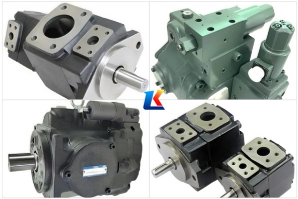
This document details the models, key parameters, technical specifications and product features of YUKEN PV2R12 and PV2R13 series double vane pumps. Both series are composed of two PV2R single vane pumps integrated into a single housing, driven by a common shaft, with one suction port and two discharge ports to supply flow to two independent hydraulic circuits respectively. They are engineered for low noise, high pressure resistance and easy maintenance, and are widely used in hydraulic systems such as machine tools, plastic injection molding machines and packaging equipment.
2. Model Designation
2.1 PV2R12 Series (Double Vane Pump)
The model designation follows a consistent YUKEN standard, explained with a typical example:
Example: PV2R12-12-33-F-REAA-43
-
PV2R: Standard YUKEN double vane pump series code
-
12: Series specification (PV2R12)
-
12: Small-volume pump nominal displacement (cm³/rev)
-
33: Large-volume pump nominal displacement (cm³/rev)
-
F: Special seal identifier for phosphate ester fluids (fluororubber seals; omitted for petroleum-based oils)
-
REAA: Mounting and port connection specification
-
43: Design number
Note: Clockwise rotation (viewed from the shaft end) is standard; counter-clockwise rotation requires customized ordering from YUKEN. Mounting options include foot mounting (L) and flange mounting (F).
2.2 PV2R13 Series (Double Vane Pump)
The model designation logic is identical to PV2R12, with a typical example:
Example: PV2R13-6-76-L-RAAA-42
-
PV2R: Double vane pump series code
-
13: Series specification (PV2R13)
-
6: Small-volume pump nominal displacement (cm³/rev)
-
76: Large-volume pump nominal displacement (cm³/rev)
-
L: Foot mounting (F for flange mounting)
-
R: Clockwise rotation (standard)
-
AAA: Port position codes (A=Upwards, E=Left 45° upwards)
-
42: Design number
Note: When using phosphate ester hydraulic fluids, add the prefix “F-” to the model to confirm the use of fluororubber seals to prevent seal damage.
3. Models and Key Parameters
The table below lists the core performance parameters, all under standard conditions (petroleum-based anti-wear hydraulic oil, 50°C operating temperature) unless otherwise stated.
|
Series
|
Small Volume Pump Displacement (cm³/rev)
|
Large Volume Pump Displacement (cm³/rev)
|
Max Rotation Speed (r/min)
|
Max Operating Pressure (bar)
|
Standard Weight (kg)
|
Shaft Speed Range (r/min)
|
|---|---|---|---|---|---|---|
|
PV2R12
|
6, 8, 10, 12, 14, 17, 19, 23, 25, 31
|
26, 33, 41, 47, 53, 59, 65
|
1800
|
210
|
25
|
600–1800
|
|
PV2R13
|
6, 8, 10, 12, 14, 17, 19, 23, 25, 31
|
76, 94, 116
|
1800
|
210
|
45.6
|
600–1800
|
Common model examples include (but are not limited to): PV2R12-10-33-F-REAA-43, PV2R12-23-65-F-REAA-43, PV2R13-6-76-L-RAAA-42, PV2R13-31-116-F-RAAA-43.
4. Additional Technical Parameters
4.1 Suction Pressure Requirements
-
For shaft speeds below 1700 r/min, the minimum suction pressure is recommended to be -20 kPa (absolute pressure, petroleum-based oil).
-
For shaft speeds between 1700–1800 r/min, especially for PV2R13 large-displacement models (94, 116 cm³/rev), the minimum suction pressure should be 0 kPa (avoid negative pressure suction to prevent cavitation).
-
Suction pressure must not be lower than -30 kPa under any operating conditions.
4.2 Hydraulic Fluid Requirements
-
Recommended fluids: Petroleum-based anti-wear hydraulic oil (ISO VG 32/46/68); water-glycol, oil-in-water emulsion (special material compatibility required); phosphate ester (only with F-type fluororubber seals).
-
Viscosity limits: Max 200 mm²/s (910 SSU) at 950 r/min; Max 100 mm²/s (455 SSU) at 600 r/min. The optimal viscosity range is 20–40 mm²/s.
-
Fluid temperature range: 10°C to 60°C (long-term operation); avoid temperatures above 70°C to prevent oil oxidation and seal aging.
4.3 Pipe Connection Specifications
-
PV2R12: Suction port F5-20-A-10, small discharge port F5-06-A-10, large discharge port F5-10-A-10 (RC thread, Type A standard).
-
PV2R13: Suction port F5-24-A-10, small discharge port F5-06-A-10, large discharge port F5-12-A-10; optional socket welding (Type B) and butt welding (Type C) connections.
-
Port positions: Standard A (Upwards); E (Left 45° upwards) is available as an option for compact installation spaces.


