Berarma hydraulic pump 02-PSP-2-40- FHRM
1. Safety Precautions
Read this manual carefully before installation, operation, and maintenance to ensure safe and efficient operation of the pump. Improper installation, operation, or maintenance may cause pump damage, performance degradation, or even safety accidents, and the resulting losses shall be borne by the user.
-
Do not operate the pump beyond the specified pressure, speed, and temperature range to avoid component failure.
-
Ensure the hydraulic system is depressurized and the power is cut off before disassembling, maintaining, or adjusting the pump.
-
Use only compatible hydraulic oil and replace it regularly to prevent oil contamination from damaging the pump components.
-
Avoid direct contact with rotating parts during operation to prevent personal injury.
-
Check the pump and pipeline for leaks regularly. If any leak is found, stop the machine immediately for maintenance.
2. Product Overview
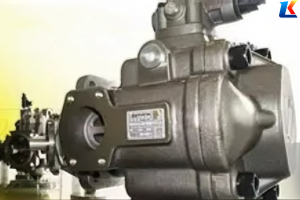
The Berarma 02-PSP-2-40-FHRM is a hydraulic compensation variable vane pump, designed for medium and high-pressure hydraulic systems. It features stable flow output, fast variable response, low noise, and high efficiency, widely used in machinery, metallurgy, engineering, and other industrial fields.
The pump adopts a modular design, which allows flexible conversion between different compensation types without special modifications to the pump body. It is equipped with standard high-pressure seals and flange mounting, ensuring reliable performance and easy installation.
3. Model Code Interpretation
The model code 02-PSP-2-40-F-H-R-M follows Berarma’s universal naming rule, and each segment is interpreted as follows:
|
Code Segment
|
Meaning
|
Description
|
|---|---|---|
|
02
|
Series Code
|
Represents Berarma standard pump series, with universal installation dimensions for the same series.
|
|
PSP
|
Product Series
|
Hydraulic compensation variable vane pump (distinguished from PLP mechanical compensation and PVS double compensation pumps).
|
|
2
|
Size Class
|
Size 2, which is linked to displacement and working pressure.
|
|
40
|
Geometric Displacement
|
40 cm³/rev (displacement per revolution, a core parameter for model selection).
|
|
F
|
Connection Type
|
Flange mounting (G = thread, S = sleeve).
|
|
H
|
Seal Type
|
High-pressure seal, suitable for 160bar working pressure (default configuration).
|
|
R
|
Rotation Direction
|
Clockwise (viewed from the shaft end; R = right, L = left).
|
|
M
|
Special Configuration
|
Standard configuration (K = pressure cut-off, Q = flow limitation).
|
4. Technical Specifications
4.1 Core Performance Parameters
|
Parameter Item
|
Specification Value
|
Remarks
|
|---|---|---|
|
Geometric Displacement
|
40 cm³/rev
|
Core selection parameter
|
|
Maximum Working Pressure
|
160 bar
|
Size 2 standard pressure
|
|
Maximum Flow at 1450rpm
|
58 L/min
|
Calculation formula: Flow = Displacement × Rotation Speed × 60 ÷ 1000
|
|
Allowable Rotation Speed Range
|
800~1800 rpm
|
Recommended rated speed: 1450rpm; flow decreases significantly below 800rpm
|
|
Control Oil Pressure
|
0.8~1.6 MPa
|
Necessary for hydraulic compensation; flow ≥ 0.5 L/min
|
|
Noise Level
|
63~72 dB(A)
|
Low noise operation
|
|
Medium Viscosity
|
10~100 cSt
|
Recommended: HM/HLP 32~46 anti-wear hydraulic oil
|
|
Operating Medium Temperature
|
10~60℃
|
Inlet oil temperature ≤ 50℃; maximum ≤ 70℃
|
|
Weight
|
6 kg
|
Including motor bracket, excluding motor (Size 2 standard weight)
|
4.2 Size and Installation Parameters
|
Parameter Item
|
Specification Value
|
|---|---|
|
Mounting Flange
|
ISO 40 (4-hole flange, UNI ISO 3019/2)
|
|
Shaft Diameter
|
16 mm
|
|
Anchor Bolt Specification
|
M10
|
|
Overall Dimensions (L×W×H)
|
220×150×180 mm
|
|
Suction Port
|
G1/2~G2 (hard pipe recommended, length ≤ 1.5m)
|
|
Discharge Port
|
G1/4~G1 (pressure resistance ≥ 21MPa)
|
|
Drain Port
|
G1/4 (must be connected to the oil tank separately, not to the return manifold)
|
|
Control Oil Interface
|
G1/8 (side compensation oil port, independent oil circuit connection)
|
5. Installation Instructions
5.1 Installation Preparation
-
Site Requirements: The installation site shall be dry, well-ventilated, free of corrosive gases, dust, and severe vibration. Avoid installing near high-temperature equipment. Reserve sufficient space for disassembly and maintenance (not less than 1.5 times the pump size).
-
Component Inspection: Check the pump appearance for collisions, damage, or deformation; ensure seals are not aged or damaged; verify that the nameplate information is clear and consistent with the model required. Rotate the pump shaft by hand to ensure it is smooth, free of jamming, and no abnormal noise; check that vanes expand and contract flexibly without looseness.
-
Tool and Material Preparation: Prepare hexagon wrench, torque wrench, screwdriver, seals, hydraulic oil (meeting viscosity requirements), cleaning cloth, sealant, etc. All tools shall be clean and free of oil stains to avoid impurities entering the pump.
5.2 Installation Steps
-
Fix the Pump: Place the pump on the installation base, adjust the level (horizontal deviation ≤ 0.1mm/m), and fix it firmly with bolts. The bolt tightening torque shall comply with official requirements (generally 8-12N·m) to avoid vibration caused by looseness. The installation base shall be firm to prevent vibration from being transmitted to the pump.
-
Connect the Motor: Connect the motor and the pump through a coupling, ensuring the coaxiality error ≤ 0.05mm and the end face parallelism ≤ 0.03mm. Avoid excessive coaxiality deviation, which may cause noise, vibration, and bearing damage. Do not directly knock the pump shaft or motor shaft to prevent shaft deformation.
-
Connect Pipelines: Connect the pipelines according to the “suction port” and “discharge port” marked on the pump nameplate. The suction pipeline shall be short and straight to reduce elbows and resistance, with good sealing to prevent air suction. The discharge pipeline shall be of appropriate specification according to the system pressure to avoid blockage or leakage. Clean the pipeline before connection to remove internal impurities and oil stains; tighten the joints after connection to ensure no looseness. The drain port must be connected to the oil tank separately, not to the return manifold.
-
Install Seals: Install new seals on the pump end cover, flange, and other connection parts, apply an appropriate amount of sealant (avoid excessive entry into the pump body) to ensure reliable sealing and prevent hydraulic oil leakage.
-
Fill with Hydraulic Oil: Fill the oil tank with hydraulic oil that meets the requirements, and the oil level shall reach the specified scale of the oil tank to ensure the pump suction port is completely submerged in the oil to avoid air suction. It is recommended to use HM/HLP 32~46 anti-wear hydraulic oil, and strictly filter the oil during filling to prevent impurities from entering the system.
-
Exhaust Treatment: Open the exhaust valve of the pump or system, manually rotate the pump shaft for several turns to drain the air in the pump and pipeline, avoiding cavitation, noise, and unstable pressure during operation. Close the exhaust valve after exhaust is completed.
-
Pre-start Inspection: Reconfirm that the pump is firmly installed, the pipeline connection is reliable, the hydraulic oil level is normal, the exhaust is completed, the motor rotation direction is correct, and there is no foreign object blocking the pump shaft rotation.
6. Operation Instructions
6.1 Pre-start Check
Before starting the pump, check the following items to ensure safe operation:
-
Hydraulic oil level and quality: Ensure the oil level is within the specified range and the oil is free of impurities, water, or deterioration.
-
Pipeline connection: Check for loose joints or leaks in the suction, discharge, and drain pipelines.
-
Control oil circuit: Ensure the control oil pressure is within the range of 0.8~1.6MPa, and the oil circuit is unobstructed.
-
Motor rotation direction: Confirm that the motor rotation direction is consistent with the pump’s rotation direction (clockwise, viewed from the shaft end).
6.2 Start-up Operation
-
Start the motor and run it at low speed (500~800rpm) for 2~3 minutes to allow the hydraulic oil to circulate and lubricate all components of the pump.
-
Gradually increase the motor speed to the rated speed (1450rpm), and observe the pump’s operation status: no abnormal noise, no oil leakage, and stable pressure and flow.
-
After the pump runs stably, adjust the system pressure to the required working pressure (not exceeding 160bar) according to the actual working conditions.
6.3 Operation Precautions
-
During operation, monitor the pump’s working pressure, temperature, and noise at any time. If abnormal phenomena (such as excessive pressure, overheating, or abnormal noise) are found, stop the machine immediately for inspection and troubleshooting.
-
Do not adjust the pressure regulating device or displacement limiter at will during operation to avoid component damage.
-
Avoid long-term operation of the pump at the maximum pressure and maximum speed to extend the service life of the pump.
-
Do not cut off the control oil circuit during operation, otherwise, the variable mechanism will fail.
7. Maintenance and Maintenance
7.1 Daily Maintenance
-
Check the hydraulic oil level and supplement it in time if it is insufficient; check the oil quality regularly, and if the oil is discolored, emulsified, or contains impurities, replace it immediately.
-
Check the pump and pipeline for leaks every day, and tighten the loose joints or replace the seals in time.
-
Clean the filter of the suction port regularly (recommended to clean once a week) to prevent blockage and affect the pump’s suction performance.
-
After the pump stops working, clean the surface of the pump to remove dust and oil stains.
7.2 Regular Maintenance
|
Maintenance Cycle
|
Maintenance Content
|
|---|---|
|
Every 1000 hours of operation
|
1. Replace the hydraulic oil and clean the oil tank; 2. Replace the oil filter element; 3. Check the wear of the pump shaft and bearing; 4. Check the elasticity and wear of the vanes and stator.
|
|
Every 2000 hours of operation
|
1. Disassemble the pump and inspect all components for wear, deformation, or damage; 2. Replace the worn seals, vanes, and other易损 parts; 3. Calibrate the pressure regulating device and variable mechanism; 4. Check the coaxiality of the pump and motor.
|
|
Every 5000 hours of operation
|
1. Conduct a comprehensive overhaul of the pump; 2. Replace the bearing, rotor, stator, and other key components if necessary; 3. Check the overall performance of the pump and adjust it to meet the standard requirements.
|
7.3 Storage Requirements
-
If the pump is not used for a long time, drain the hydraulic oil in the pump and pipeline, clean the pump body and components, and apply anti-rust oil to the rotating parts and joint surfaces.
-
Store the pump in a dry, ventilated, and cool place, avoid direct sunlight and rain, and prevent corrosion and damage to the pump body.
-
When storing, place the pump horizontally, and pad the bottom to avoid collision and deformation of the pump shaft and flange.
8. Troubleshooting
|
Fault Phenomenon
|
Possible Causes
|
Solution
|
|---|---|---|
|
Insufficient or no output flow
|
1. Low hydraulic oil level or blocked suction filter; 2. Air in the pump or pipeline; 3. Wear of vanes or stator; 4. Control oil pressure is too low; 5. Rotation direction is wrong.
|
1. Supplement hydraulic oil and clean the suction filter; 2. Exhaust the air in the pump and pipeline; 3. Replace worn vanes or stator; 4. Adjust the control oil pressure to 0.8~1.6MPa; 5. Correct the motor rotation direction.
|
|
Unstable working pressure
|
1. Air in the system; 2. Damage to the pressure regulating device; 3. Leakage in the pipeline; 4. Excessive viscosity of hydraulic oil.
|
1. Exhaust the air in the system; 2. Repair or replace the pressure regulating device; 3. Tighten the pipeline joints or replace the seals; 4. Replace the hydraulic oil with appropriate viscosity.
|
|
Excessive noise during operation
|
1. Air in the pump; 2. Coaxiality deviation between pump and motor; 3. Wear of bearing or pump shaft; 4. Blocked suction pipeline; 5. Loose pump installation.
|
1. Exhaust the air; 2. Adjust the coaxiality to meet the requirements; 3. Replace the bearing or pump shaft; 4. Clean the suction pipeline; 5. Tighten the installation bolts.
|
|
Oil leakage
|
1. Aged or damaged seals; 2. Loose pipeline joints; 3. Excessive system pressure; 4. Deformation of pump end cover or flange.
|
1. Replace the seals; 2. Tighten the pipeline joints; 3. Adjust the system pressure to the specified range; 4. Repair or replace the deformed end cover or flange.
|
|
Pump overheating
|
1. Excessive viscosity of hydraulic oil; 2. Poor heat dissipation of the system; 3. Wear of internal components leading to increased friction; 4. Long-term operation at maximum pressure.
|
1. Replace the hydraulic oil with appropriate viscosity; 2. Check and improve the system heat dissipation; 3. Replace worn internal components; 4. Avoid long-term operation at maximum pressure.
|
9. Replacement and After-sales Service
The 02-PSP-2-40-FHRM pump may be replaced by the Berarma PHP series (e.g., 01-PHP-2-40-FHRM), which is an upgraded version with a maximum pressure increased to 210bar. For detailed differences between the two series, please contact Berarma official after-sales service or authorized distributors.
If you encounter any problems during installation, operation, or maintenance that cannot be solved by this manual, please contact Berarma technical support or local authorized distributors for assistance. We will provide you with professional technical guidance and after-sales service.
Note: All technical parameters and structural details in this manual are based on the product at the time of publication. Berarma reserves the right to modify the product design and parameters without prior notice. For the latest information, please refer to the official website or contact the after-sales service.


