Product manual of Vickers vane pump V10/V20 series
1. Introduction
1.1 Product Overview
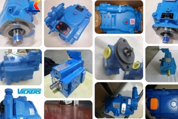
The Vickers V10 and V20 series are high-performance fixed displacement balanced vane pumps, specifically engineered to cater to the diverse needs of modern mobile and industrial hydraulic systems. With a compact and robust design, these pumps deliver exceptional efficiency, reliability, and long service life, making them ideal for applications such as machine tools, construction equipment, agricultural machinery, and industrial hydraulic circuits. The series is available in both single and double pump configurations, providing flexible solutions for various flow and pressure requirements.
A key design feature of the V10/V20 series is the diametrically opposed internal inlet and outlet pressure chambers, which effectively balance pressure-induced radial loads. This balance significantly reduces bearing stress, minimizes wear, and extends the overall service life of the pump, even under continuous operation in harsh working environments.
1.2 Scope of Application
-
Industrial machinery: Machine tools, hydraulic presses, plastic injection molding machines, and conveyor systems.
-
Mobile equipment: Construction machinery, agricultural tractors, forklifts, and utility vehicles.
-
Other applications: Hydraulic power units, test benches, and any system requiring a reliable, compact fixed displacement pump.
1.3 Safety Precautions
-
Before installation, operation, or maintenance, ensure that all personnel involved have read and understood this manual thoroughly.
-
Always shut off the power supply and relieve system pressure before performing any maintenance or disassembly work to avoid personal injury or equipment damage.
-
Do not operate the pump beyond the specified maximum pressure, speed, or temperature limits, as this may lead to pump failure, oil leakage, or fire hazards.
-
Use only recommended hydraulic fluids and maintain proper fluid cleanliness to prevent internal component wear and blockages.
-
Wear appropriate personal protective equipment (PPE), such as safety glasses, gloves, and protective clothing, when working with the pump or hydraulic system.
2. Technical Specifications
2.1 General Technical Parameters
-
Inlet Pressure: Recommended 0 to 0.34 bar (0 to 5 psi) gauge; maximum inlet pressure should not exceed 1.38 bar (20 psi); inlet depressions should not exceed 0.17 bar (5” of Hg or 12.2 psia).
-
Minimum Starting Speed: Generally 600 r/min under standard fluid conditions (SAE 10W oil at 38 to 82°C), which may vary based on pump size, system characteristics and environmental conditions.
-
Fluid Viscosity: Permissible viscosity range is 860 to 40 cst (4000 to 180 sus) when operating with SAE 10W oil, with oil temperature ranging from -12 to 35°C (10 to 95°F).
-
Maximum Continuous Pressure: Up to 172 bar (2500 psi) for most models; some models have lower maximum pressure as specified in the detailed table below.
-
Operating Temperature Range: -12°C to 82°C (10°F to 180°F); avoid prolonged operation at temperatures above 82°C to prevent fluid degradation and component damage.
-
Fluid Recommendation: SAE 10W, 20W hydraulic oil or equivalent, meeting ISO VG 32 or VG 46 standards; ensure fluid is clean, free of contaminants (maximum contamination level: ISO 18/16/13).
2.2 Detailed Model Specifications
Note: All values are theoretical, excluding efficiency and tolerances, and rounded to a reasonable precision. For double pump configurations, please refer to the separate technical data sheet or contact the manufacturer.
2.2.1 V10 Series Single Vane Pump
|
Model Code
|
Geometric Displacement (cm³/r / in³/r)
|
Maximum Pressure (bar / psi)
|
Maximum Speed (rpm)
|
Delivery at 1500 rpm & 7 bar (l/min / usgpm)
|
Minimum Speed (rpm)
|
|---|---|---|---|---|---|
|
V10-1
|
3.3 / 0.20
|
172 / 2500
|
4800
|
4.70 / 1.25
|
650
|
|
V10-2
|
6.6 / 0.40
|
172 / 2500
|
4500
|
9.40 / 2.50
|
650
|
|
V10-3
|
9.8 / 0.60
|
172 / 2500
|
4000
|
14.20 / 3.75
|
650
|
|
V10-4
|
13.1 / 0.80
|
172 / 2500
|
3400
|
18.90 / 5.00
|
650
|
|
V10-5
|
16.4 / 1.00
|
172 / 2500
|
3200
|
23.60 / 6.25
|
650
|
|
V10-6
|
19.5 / 1.19
|
152 / 2200
|
3000
|
28.40 / 7.50
|
650
|
|
V10-7
|
22.8 / 1.39
|
138 / 2000
|
2800
|
33.10 / 8.75
|
650
|
2.2.2 V20 Series Single Vane Pump
|
Model Code
|
Geometric Displacement (cm³/r / in³/r)
|
Maximum Pressure (bar / psi)
|
Maximum Speed (rpm)
|
Delivery at 1500 rpm & 7 bar (l/min / usgpm)
|
Minimum Speed (rpm)
|
|---|---|---|---|---|---|
|
V20-6
|
19.5 / 1.19
|
172 / 2500
|
3400
|
28.39 / 7.50
|
650
|
|
V20-7
|
22.8 / 1.39
|
172 / 2500
|
3000
|
33.11 / 8.75
|
650
|
|
V20-8
|
26.5 / 1.62
|
172 / 2500
|
2800
|
37.85 / 10.00
|
650
|
|
V20-9
|
29.7 / 1.81
|
172 / 2500
|
2800
|
42.57 / 11.25
|
650
|
|
V20-11
|
36.4 / 2.22
|
172 / 2500
|
2500
|
52.04 / 13.75
|
650
|
|
V20-12
|
39.0 / 2.38
|
152 / 2200
|
2400
|
56.77 / 15.00
|
650
|
|
V20-13
|
42.4 / 2.59
|
152 / 2200
|
2400
|
61.50 / 16.25
|
650
|
3. Installation Instructions
3.1 Installation Preparation
-
Inspect the pump for any damage or missing components before installation. Check the packaging for signs of transit damage and verify that all parts are intact.
-
Ensure the installation location is clean, dry, and well-ventilated, with sufficient space for maintenance and access to the pump’s ports and mounting points.
-
Prepare the mounting surface: It should be flat, smooth, and able to support the pump’s weight and operating vibrations. Clean the surface to remove any dirt, grease, or debris.
-
Select appropriate mounting hardware (bolts, washers) that match the pump’s mounting holes and can withstand the operating loads. Use lock washers or thread locker to prevent bolt loosening due to vibration.
3.2 Mounting the Pump
-
Position the pump on the mounting surface, aligning the mounting holes with the holes on the surface. Ensure the pump is level and properly aligned with the drive shaft (if connected to a motor).
-
Insert the mounting bolts through the pump’s mounting holes and tighten them evenly to the recommended torque (refer to the torque specifications provided in the appendix).
-
If the pump is connected to a motor, ensure the drive shaft alignment is correct (maximum misalignment: 0.1 mm radial, 0.05 mm axial). Use a flexible coupling to reduce vibration transfer and compensate for minor misalignment.
-
Connect the inlet and outlet hoses/pipes to the pump’s ports. Ensure the connections are tight to prevent oil leakage. Use appropriate fittings that match the port size (refer to the model specifications for port dimensions).
3.3 Post-Installation Check
-
Verify that all connections are secure and there are no loose components.
-
Fill the hydraulic system with the recommended hydraulic fluid, ensuring the fluid level is within the specified range.
-
Prime the pump by manually turning the drive shaft (if possible) to ensure the pump is filled with fluid and air is purged from the system.
-
Check for any oil leaks before starting the pump. Tighten any loose connections if leaks are detected.
4. Operation Guidelines
4.1 Startup Procedure
-
Ensure the power supply is connected and the hydraulic system is properly filled with fluid.
-
Turn on the power and start the pump at low speed (approximately 500-600 rpm) to allow the fluid to circulate and the pump to warm up.
-
Monitor the pump’s operation for any unusual noise, vibration, or overheating. Normal operation should be quiet and smooth, with no excessive vibration.
-
Gradually increase the speed to the operating speed and check the system pressure. Ensure the pressure does not exceed the pump’s maximum rated pressure.
-
Verify that the fluid temperature remains within the recommended range (-12°C to 82°C). If the temperature exceeds 82°C, check the cooling system and ensure proper fluid flow.
4.2 Normal Operation
-
Operate the pump within the specified pressure and speed limits at all times. Avoid prolonged operation at or near the maximum rated pressure, as this may reduce service life.
-
Regularly monitor the fluid level and condition. Check for fluid contamination (e.g., dirt, water) and replace the fluid if necessary.
-
Inspect the pump for oil leaks during operation. Address any leaks immediately to prevent fluid loss and potential system damage.
-
Do not shut down the pump abruptly while it is operating at high pressure. Gradually reduce the pressure and speed before shutting off the power.
4.3 Shutdown Procedure
-
Reduce the pump’s speed to low (500-600 rpm) and relieve the system pressure.
-
Turn off the power supply to stop the pump.
-
If the pump will not be used for an extended period (more than 30 days), drain the hydraulic fluid and store the pump in a clean, dry environment. Protect the ports with caps or plugs to prevent contamination.
5. Maintenance and Servicing
5.1 Routine Maintenance Schedule
|
Maintenance Item
|
Frequency
|
Maintenance Content
|
|---|---|---|
|
Fluid Level Check
|
Daily
|
Check the hydraulic fluid level and add fluid if necessary to maintain the recommended level.
|
|
Fluid Condition Check
|
Weekly
|
Inspect the fluid for color, clarity, and contamination. Replace fluid if it is cloudy, discolored, or contains debris.
|
|
Leak Check
|
Weekly
|
Inspect all connections, seals, and the pump housing for oil leaks. Tighten connections or replace seals as needed.
|
|
Filter Replacement
|
Every 250 hours of operation or 6 months (whichever comes first)
|
Replace the hydraulic filter to prevent contamination of the pump and system components.
|
|
Fluid Replacement
|
Every 1000 hours of operation or 12 months (whichever comes first)
|
Drain the old fluid, flush the system, and refill with fresh, recommended hydraulic fluid.
|
|
Bearing Inspection
|
Every 2000 hours of operation
|
Check the pump’s bearings for noise, vibration, or excessive play. Replace bearings if necessary.
|
5.2 Common Troubleshooting
|
Trouble Symptom
|
Possible Cause
|
Solution
|
|---|---|---|
|
Pump fails to start or run
|
1. Power supply failure; 2. Drive shaft jammed; 3. Pump is not primed; 4. Fluid viscosity is too high.
|
1. Check power supply and connections; 2. Inspect drive shaft for jamming and clear obstacles; 3. Prime the pump manually; 4. Heat the fluid to reduce viscosity.
|
|
Low flow or pressure
|
1. Fluid level is too low; 2. Inlet filter is clogged; 3. Leaks in the inlet line; 4. Vane wear or damage.
|
1. Add fluid to the recommended level; 2. Clean or replace the inlet filter; 3. Repair or replace the inlet line; 4. Disassemble the pump and replace worn vanes.
|
|
Excessive noise or vibration
|
1. Drive shaft misalignment; 2. Air in the system; 3. Bearings are worn; 4. Fluid is contaminated.
|
1. Adjust the drive shaft alignment; 2. Purge air from the system; 3. Replace worn bearings; 4. Replace the hydraulic fluid and clean the system.
|
|
Overheating
|
1. Fluid level is too low; 2. Cooling system failure; 3. Operating pressure exceeds rated limit; 4. Fluid viscosity is incorrect.
|
1. Add fluid to the recommended level; 2. Inspect and repair the cooling system; 3. Reduce operating pressure to within rated limits; 4. Replace fluid with the recommended viscosity.
|
|
Oil leakage
|
1. Loose connections; 2. Worn or damaged seals; 3. Cracked pump housing; 4. Overpressure in the system.
|
1. Tighten loose connections; 2. Replace worn or damaged seals; 3. Replace the pump housing if cracked; 4. Reduce system pressure to within rated limits.
|
5.3 Disassembly and Reassembly
Disassembly and reassembly should only be performed by qualified personnel with proper tools and knowledge. Follow these general steps:
-
Shut off the power supply and relieve system pressure. Disconnect the inlet and outlet hoses/pipes and the drive shaft coupling.
-
Remove the mounting bolts and lift the pump from the mounting surface.
-
Disassemble the pump in the following order: end cover, vanes, rotor, cam ring, and bearing assembly. Use proper tools to avoid damaging components.
-
Clean all components thoroughly with a suitable cleaning agent. Inspect each component for wear, damage, or deformation. Replace any worn or damaged parts with genuine Vickers replacement parts.
-
Reassemble the pump in the reverse order of disassembly. Ensure all components are properly aligned and seated. Apply a thin layer of hydraulic fluid to the vanes, rotor, and cam ring before assembly.
-
Reinstall the pump on the mounting surface, reconnect the hoses/pipes and drive shaft coupling, and perform the post-installation check before restarting.
6. Storage and Handling
-
Store the pump in a clean, dry, and well-ventilated area, away from direct sunlight, extreme temperatures, and corrosive substances.
-
Keep the pump in its original packaging until installation to prevent damage and contamination.
-
If the pump is stored for more than 30 days, fill it with a preservative fluid (or the recommended hydraulic fluid) to prevent internal corrosion. Cap or plug all ports to keep out dirt and moisture.
-
When handling the pump, use proper lifting equipment (if necessary) to avoid injury. Do not drop or strike the pump, as this may damage internal components.
7. Warranty Information
The Vickers V10/V20 series vane pumps are covered by a standard 12-month warranty from the date of installation or 18 months from the date of shipment, whichever comes first. The warranty covers defects in materials and workmanship under normal operating conditions. The warranty does not cover damage caused by improper installation, operation, maintenance, misuse, abuse, or unauthorized modification. For warranty claims, contact the authorized Vickers distributor or manufacturer with the pump’s model number, serial number, and details of the defect.
8. Appendix
8.1 Torque Specifications for Mounting Bolts
|
Bolt Size
|
Torque (N·m / lbf·ft)
|
|---|---|
|
M8
|
18-22 / 13-16
|
|
M10
|
35-40 / 26-30
|
|
M12
|
60-65 / 44-48
|
8.2 Contact Information
For technical support, spare parts, or additional information, contact your local Vickers authorized distributor or visit the official Vickers website. Provide the pump’s model number and serial number when requesting assistance to ensure accurate and timely support.


