Berarma vane pump 01-PHP-05-16- FHRM manual
1. Product Overview
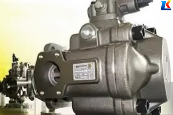
The Berarma 01-PHP-05-16-FHRM is a high-pressure variable displacement vane pump belonging to the PHP series, designed and manufactured by Italian Berarma S.r.l. This model features compact structure, high efficiency, low noise, and long service life, making it suitable for various industrial hydraulic systems that require stable high-pressure output, such as injection molding machines, die-casting machines, and metallurgical equipment.
As a member of the PHP series, this pump is equipped with a hydraulic pressure regulating device, which can instantly adjust the flow rate according to the circuit requirements, realizing energy saving and simplification of the hydraulic system. Its modular design also facilitates maintenance and component replacement.
2. Technical Parameters
|
Parameter
|
Specification
|
Unit
|
|
Model
|
01-PHP-05-16-FHRM
|
–
|
|
Product Series
|
PHP
|
–
|
|
Type
|
Variable Displacement Vane Pump
|
–
|
|
Nominal Displacement
|
16
|
cm³/rev
|
|
Max. Working Pressure
|
250
|
bar
|
|
Flow Rate (at 1450 rpm)
|
23
|
L/min
|
|
Size Class
|
05 (Small)
|
–
|
|
Mounting Flange
|
F (ISO 3019/2)
|
–
|
|
Shaft Extension Type
|
H (Standard Shaft)
|
–
|
|
Rotation Direction
|
R (Clockwise)
|
–
|
|
Seal Material
|
M (NBR Rubber)
|
–
|
|
Recommended Hydraulic Oil
|
ISO VG 32/46 Hydraulic Oil
|
–
|
|
Working Temperature Range
|
-10 ~ 80
|
℃
|
|
Max. Rotational Speed
|
3000
|
rpm
|
3. Installation Instructions
3.1 Installation Preparation
-
Check the pump appearance for damage, deformation, or oil leakage before installation. Ensure all components (rotor, vanes, seals) are intact and properly assembled.
-
Verify that the installation surface is clean, flat, and free of debris. The mounting flange (ISO 3019/2) should be aligned with the equipment’s mounting surface to ensure good fit.
-
Prepare the required tools (wrenches, screwdrivers, torque wrench) and accessories (mounting bolts, gaskets) that match the pump specifications.
-
Select the appropriate hydraulic oil according to the working environment and fill the system with oil to the specified level.
3.2 Installation Steps
-
Fix the pump to the equipment’s mounting surface using the matching bolts. Tighten the bolts evenly with a torque wrench to avoid uneven stress on the pump body; the recommended torque is 25-30 N·m.
-
Connect the pump shaft to the motor shaft using an elastic coupling. Ensure the coaxiality of the two shafts is ≤ 0.1 mm to prevent bearing damage caused by misalignment. Reserve a certain axial clearance for the coupling to avoid stress on the shaft head.
-
Connect the oil inlet and outlet pipelines. The inlet pipeline should be as short and straight as possible to reduce suction resistance; the outlet pipeline should be equipped with a pressure gauge to monitor the working pressure in real time.
-
Open the exhaust valve on the pump to release air in the pipeline and pump body. Fill the pump with hydraulic oil manually to prevent dry friction during startup.
-
Check all connections (flange, pipeline, bolts) for looseness or oil leakage. Confirm that the rotation direction of the motor matches the pump’s rotation direction (clockwise, R) before powering on.
3.3 Installation Notes
-
Do not knock the pump body or shaft forcefully during installation, as this may damage internal components such as bearings and vanes.
-
Avoid over-tightening the coupling, as excessive fit clearance may damage the bearing and affect the service life of the pump core.
-
The installation environment should be well-ventilated, away from high-temperature heat sources and corrosive substances.
4. Operation Guidelines
4.1 Pre-Startup Check
-
Check the hydraulic oil level and quality: the oil level should be between the upper and lower scales of the oil tank, and the oil should be clean, free of impurities, and not emulsified or deteriorated.
-
Verify that the pressure gauge, pressure relief valve, and other control components are working normally.
-
Manually rotate the pump shaft 2-3 turns to ensure smooth rotation without jamming or abnormal noise.
4.2 Startup Operation
-
Start the motor at low speed (500-800 rpm) and run it for 2-3 minutes to allow the hydraulic oil to circulate and lubricate all components.
-
Gradually increase the motor speed to the rated speed (1450 rpm) and observe the pressure gauge reading. The initial pressure should be within 50-100 bar; if the pressure is too high or too low, adjust the pressure relief valve in time.
-
Check for oil leakage at all connections and listen for abnormal noises (such as grinding or whining), which may indicate worn or misaligned parts.
4.3 Normal Operation
-
Maintain the working pressure within the range of 0-250 bar; do not exceed the maximum pressure for a long time to avoid damage to the pump.
-
Monitor the hydraulic oil temperature: if the temperature exceeds 80℃, stop the machine to cool down and check the cooling system.
-
Avoid sudden load changes or frequent start-stop, which may affect the service life of the pump.
4.4 Shutdown Operation
-
Reduce the motor speed to low speed and run for 1-2 minutes to release the system pressure.
-
Turn off the motor and cut off the power supply.
-
Close the oil inlet and outlet valves (if equipped) to prevent hydraulic oil backflow.
-
Clean the pump surface and surrounding area, and record the operation time and working status for future maintenance reference.
5. Maintenance and Maintenance
5.1 Regular Maintenance Cycle
|
Maintenance Item
|
Cycle
|
Maintenance Content
|
|
Daily Inspection
|
Every Working Day
|
Check oil level, pressure, noise, and oil leakage; clean the pump surface.
|
|
Oil Filter Replacement
|
Every 200 Working Hours
|
Replace the oil filter element to prevent oil contamination from damaging internal components.
|
|
Hydraulic Oil Replacement
|
Every 1000 Working Hours
|
Drain the old oil, clean the oil tank, and refill with new hydraulic oil that meets the specifications.
|
|
Seal Inspection and Replacement
|
Every 1500 Working Hours
|
Check the seal ring for aging, wear, or damage; replace if necessary to prevent oil leakage.
|
|
Internal Component Inspection
|
Every 3000 Working Hours
|
Disassemble the pump to check the wear of vanes, rotor, and stator; replace worn components to ensure stable performance.
|
5.2 Maintenance Notes
-
Disconnect the power supply and release the system pressure before maintenance to ensure operational safety.
-
Use original Berarma spare parts (vanes, seals, bearings) for replacement to ensure compatibility and performance.
-
Clean all components during disassembly and assembly to avoid impurities entering the pump body, which may cause internal wear.
-
After maintenance, reassemble the pump correctly and conduct a test run to confirm no abnormal noise or oil leakage.
6. Troubleshooting
|
Fault Phenomenon
|
Possible Causes
|
Solution
|
|
No Oil Output or Insufficient Flow
|
1. Air in the pump body; 2. Clogged oil inlet pipeline; 3. Worn vanes or rotor; 4. Low oil level.
|
1. Open the exhaust valve to release air; 2. Clean the inlet pipeline; 3. Replace worn vanes or rotor; 4. Add hydraulic oil to the specified level.
|
|
Excessively High Working Pressure
|
1. Malfunction of the pressure relief valve; 2. Blocked outlet pipeline; 3. Incorrect pressure setting.
|
1. Inspect and repair the pressure relief valve; 2. Clean the outlet pipeline; 3. Adjust the pressure to the specified range.
|
|
Abnormal Noise (Grinding/Whining)
|
1. Misaligned pump and motor shafts; 2. Worn bearings or vanes; 3. Insufficient lubrication; 4. Air in the system.
|
1. Adjust the coaxiality of the shafts; 2. Replace worn bearings or vanes; 3. Check the oil level and oil quality; 4. Release air in the system.
|
|
Oil Leakage
|
1. Aging or damaged seal ring; 2. Loose mounting bolts; 3. Damaged flange surface.
|
1. Replace the seal ring; 2. Tighten the mounting bolts; 3. Repair or replace the flange.
|
|
Overheating of the Pump
|
1. Excessive working pressure; 2. Poor heat dissipation of the system; 3. Contaminated or deteriorated hydraulic oil.
|
1. Reduce the working pressure; 2. Check and repair the cooling system; 3. Replace the hydraulic oil.
|
7. Safety Precautions
-
Operators must be familiar with this instruction manual and relevant safety regulations before operating the pump. Unauthorized operation is prohibited.
-
Do not touch the pump body, pipeline, or other high-temperature components during operation to avoid burns.
-
Do not disassemble or maintain the pump while it is running or under pressure to prevent hydraulic oil spraying and personal injury.
-
Keep the working area clean and tidy. Avoid placing tools, debris, or flammable substances near the pump to prevent accidents.
-
If the pump fails during operation, stop the machine immediately, cut off the power supply, and troubleshoot according to the troubleshooting guide. Do not force operation to avoid further damage.


