Vickers hydraulic piston Pump PVH series product manual
1. Introduction
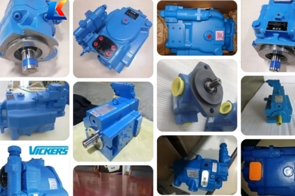
The Vickers PVH Series is a premium line of variable displacement axial piston pumps developed by Danfoss Power Solutions (formerly Eaton Vickers), engineered to deliver exceptional performance, durability, and efficiency for high-pressure industrial and mobile hydraulic applications. Built with advanced precision manufacturing and a robust swashplate design, the PVH Series is specifically optimized to handle extreme operating conditions, including high continuous and intermittent pressures, variable flow demands, and harsh environmental factors. These pumps are widely utilized in heavy-duty machinery, hydraulic power units, construction equipment, mining machinery, marine systems, and other critical applications where reliability and performance are paramount.
This manual provides comprehensive, step-by-step instructions for the safe installation, operation, maintenance, and troubleshooting of Vickers PVH Series hydraulic piston pumps. Adherence to the guidelines and specifications outlined herein is essential to ensure optimal pump performance, extend service life, prevent equipment damage, and protect personnel from potential hazards. All information contained in this manual is based on the latest product design and engineering standards, and it is recommended to refer to the most recent version for updates.
2. Safety Precautions
2.1 General Safety Guidelines
-
Only trained and qualified personnel with a thorough understanding of hydraulic systems and the PVH Series pump should perform installation, operation, maintenance, or repair work. Unauthorized access or operation may result in severe injury, equipment failure, or property damage.
-
Before conducting any work on the pump or associated hydraulic system, always relieve all system pressure, shut off the power supply, and lock out the power source to prevent accidental startup. Verify pressure relief using a calibrated pressure gauge before proceeding with any disassembly or maintenance.
-
The Vickers PVH Series pumps are classified as Group II, Category 3 equipment for gas environments, with ignition protection achieved through constructional safety and liquid immersion. The temperature class and maximum surface temperature are dependent on operating conditions (ambient and fluid temperature) and application duty cycles—refer to the pump nameplate for specific ratings.
-
Strictly comply with the maximum operating pressure, temperature, and speed limits specified for the specific PVH model. Exceeding these limits can cause catastrophic component failure, hydraulic fluid leaks, or fire hazards.
-
Never use hands or any body part to check for hydraulic fluid leaks. Escaping fluid under high pressure can penetrate the skin, causing severe injury, infection, or burns. Use a piece of cardboard or plastic to detect leaks, and wear appropriate personal protective equipment at all times.
2.2 Maintenance and Repair Safety
-
Thoroughly clean the pump and surrounding area before performing any maintenance or repair work to prevent dust, debris, or contaminants from entering the hydraulic system—contamination is the leading cause of premature pump failure.
-
Use only genuine Vickers replacement parts and accessories. Non-genuine parts may not meet the performance, safety, or dimensional standards of the PVH Series, and their use will void the product warranty and may cause equipment damage.
-
Wear appropriate personal protective equipment (PPE) when working on the pump, including safety glasses, chemical-resistant gloves, protective clothing, and steel-toed boots, to protect against fluid spills, moving parts, sharp components, and hydraulic fluid hazards.
-
Dispose of used hydraulic fluids, filters, seals, and other components in accordance with local environmental regulations. Do not dump hydraulic fluid into the environment or dispose of hazardous materials improperly.
-
Ensure proper grounding of the pump and associated equipment to eliminate static electricity buildup, which can pose a fire hazard in explosive environments. Consult Danfoss technical support for specific grounding recommendations.
3. Specifications & Performance
3.1 Core Specifications
|
Parameter
|
Specification
|
|
Displacement Range
|
25–141 cm³/r (1.53–8.6 in³/r)
|
|
Maximum Operating Pressure
|
420 bar (6090 psi) continuous; 480 bar (6960 psi) intermittent
|
|
Design Type
|
Open-circuit, axial piston, swashplate design; variable displacement
|
|
Input Rotation
|
Clockwise (right hand) or counter-clockwise (left hand); selectable at time of order
|
|
Fluid Compatibility
|
Petroleum-based hydraulic oil (ISO VG 32–68), synthetic hydraulic fluids (e.g., PAO, ester), and high-water-content fluids (HFC); consult Danfoss for phosphate ester compatibility
|
|
Operating Temperature Range
|
–25°C to 105°C (–13°F to 221°F); ambient temperature not to exceed 45°C (113°F) for continuous operation
|
|
Noise Level
|
≤ 72 dB(A) at rated speed and pressure; optimized design reduces fluid-borne and structure-borne noise
|
|
Recommended Fluid Cleanliness
|
ISO 4406 (NAS7) Class 16/14/11
|
3.2 Key Models
The PVH Series includes a range of models to accommodate diverse displacement and application requirements, including: PVH025, PVH035, PVH045, PVH057, PVH063, PVH074, PVH081, PVH098, PVH106, PVH131, PVH141. Each model is available with multiple control options to suit specific system needs, and can be configured for tandem or parallel operation in multi-pump systems.
3.3 Control Options
-
Pressure Compensator (PC): Maintains consistent system pressure by automatically adjusting pump displacement; available in high-pressure (180–420 bar) and low-pressure (40–170 bar) configurations for all models.
-
Pressure & Flow Compensator (PC/LS): Combines pressure control with load-sensing flow regulation, optimizing energy efficiency by matching pump flow to actual system demand; available with or without bleed-down orifice (Code B/C) for enhanced control flexibility.
-
Power Control / Torque Limiter: Prevents pump overload by reducing displacement as system pressure increases, limiting power output at a given speed; ideal for applications with variable load demands and peak pressure requirements.
-
Electronic Control: Available for 57–141 cc/r models, enabling remote electronic control of compensation settings with (Code E) or without (Code F) load sensing; features NFPA-D03/ISO 4401-03 interface and compatibility with industry-standard control signals (4–20 mA, 0–10 V).
-
Maximum Displacement Adjustment Stop: Allows manual tuning of maximum flow output to match specific system requirements; minimum adjustable displacement is 40% of full displacement.
4. Installation
4.1 Pump Unit Installation
-
Select a mounting location that is clean, dry, well-ventilated, and free from excessive vibration and temperature fluctuations. Ensure there is sufficient space for maintenance, access to control components, gauge ports, and hydraulic connections.
-
The mounting surface must be flat, rigid, and capable of supporting the pump’s weight and operating forces. Use the recommended mounting flange (SAE or ISO configurations available) and high-strength fasteners torqued to the specified values to secure the pump firmly.
-
Align the pump shaft with the drive motor shaft with extreme precision. Misalignment (coaxial error > 0.05 mm, angular error > 0.3°) will cause excessive wear, noise, and premature failure. Use a flexible coupling to accommodate minor misalignment and absorb vibration, and avoid over-tightening coupling fasteners.
-
Verify that the input rotation direction matches the pump’s specified rotation (marked on the pump housing). Incorrect rotation will result in no flow output, cavitation, and potential component damage.
-
When hoisting the pump, use the designated lifting rings or base—never hoist by the pump shaft, hydraulic ports, or control components, as this will damage seals, bearings, or internal parts.
4.2 Pipeline Installation
-
Use clean, debris-free hydraulic lines that are rated for the pump’s maximum operating pressure (minimum 480 bar for intermittent operation). Ensure lines are properly sized to minimize pressure drop and avoid cavitation (inlet line flow velocity ≤ 0.8 m/s, outlet line flow velocity ≤ 5.0 m/s).
-
Install inlet and outlet lines securely using compatible fittings (SAE or ISO thread standards). Avoid sharp bends, kinks, or excessive line length, especially in inlet lines, to prevent flow restriction and cavitation. Use pipe clamps to secure lines and reduce vibration transfer.
-
The pump’s housing drain port must be connected to a dedicated return line (not combined with system return lines) to ensure the housing remains filled with oil at all times. The maximum allowable housing pressure is 1.5 bar; drain line length should not exceed 1.5 meters (4.9 ft), or line size must be increased for longer runs to reduce pressure drop.
-
Install a high-quality filter in the inlet line (recommended 5–10 μm micron rating) to protect the pump’s internal components from contamination. A return line filter (3–5 μm) is also recommended for system-wide protection, and a pressure relief valve should be installed in the outlet line to prevent overpressure.
-
Remove all plastic protective caps from hydraulic ports before connecting lines to prevent debris from entering the pump. Flush all lines with clean hydraulic fluid before final connection to remove any contaminants.
4.3 Hydraulic Fluid Preparation
Fill the hydraulic system with the recommended hydraulic fluid, ensuring the fluid level is within the specified range of the reservoir. Bleed all air from the system (pump, lines, and components) to prevent cavitation, air locks, and component damage. The optimal fluid viscosity range is 18–45 cSt (95–210 SUS); maximum viscosity at startup is 1200 cSt (5460 SUS), and minimum viscosity at 105°C (221°F) is 8 cSt (75 SUS). The recommended fluid cleanliness level is ISO 4406 (NAS7) Class 16/14/11—regularly monitor fluid condition to maintain this level.
5. Operation
5.1 Pre-Startup Check
-
Inspect the pump for signs of damage, loose fasteners, or fluid leaks. Check that all hydraulic lines and fittings are secure, and that the pump housing is properly grounded.
-
Verify that the hydraulic fluid level is correct and the fluid is clean, free from contamination, discoloration, or foaming. Check the condition of filters and replace if necessary.
-
Check all control settings (pressure, flow, torque) to ensure they match the system requirements and application specifications. Verify that electronic control signals (if applicable) are properly connected and calibrated.
-
Ensure the power supply is connected correctly, and the emergency stop system is functional. Test the emergency stop to confirm it shuts down the system immediately.
-
Manually rotate the pump shaft several times (at least 5 full rotations) to distribute lubricant and expel trapped air from internal components. Do not force the shaft—if it binds, investigate the cause before proceeding.
5.2 Startup Procedure
-
Start the drive motor and run it at low speed (400–800 rpm) for 3–5 minutes to allow hydraulic fluid to circulate and lubricate all pump components. Do not apply load during this warm-up period.
-
Monitor the pump for unusual noise, vibration, or fluid leaks. Check the fluid temperature and pressure—if any abnormalities are detected (e.g., excessive noise, rapid temperature rise, leaks), shut down the system immediately, relieve pressure, and investigate the cause.
-
Gradually increase the motor speed to the rated operating speed (typically 1500–2800 rpm) and adjust the control settings to achieve the desired system pressure and flow. Verify that the pump displacement adjusts correctly in response to control signals.
-
Check the fluid temperature and pressure regularly during initial operation. Ensure the fluid temperature remains within the range of 45–85°C (113–185°F) and pressure does not exceed the pump’s maximum rating. Monitor the housing drain line for proper flow and pressure.
5.3 Normal Operation Guidelines
-
Avoid operating the pump beyond its maximum pressure, temperature, or speed limits. Sustained operation outside these limits will cause premature wear, seal damage, and component failure.
-
Monitor fluid condition regularly (daily for critical applications). Contaminated or degraded fluid is a major cause of pump damage—check for discoloration, foaming,异味, or water contamination, and replace fluid and filters according to the maintenance schedule.
-
Use the adjustable maximum displacement stop to tune flow output to the system’s actual needs, reducing energy consumption, heat generation, and wear.
-
Regularly inspect gauge ports to monitor inlet and outlet pressure, ensuring the system is operating within specifications. Record pressure and temperature readings for future reference and maintenance.
-
Avoid sudden changes in load or pressure, as this can cause hydraulic shock and damage internal components. Use pressure relief valves and accumulators (if applicable) to dampen pressure spikes.
6. Maintenance & Service
6.1 Routine Maintenance Schedule
|
Maintenance Task
|
Frequency
|
Details
|
|
Fluid Level & Condition Check
|
Daily
|
Check fluid level in reservoir; top up with recommended fluid if necessary. Inspect fluid for contamination, foaming, discoloration, or water content.
|
|
Filter Replacement
|
Every 200–400 Operating Hours
|
Replace inlet and return line filters. Clean filter housing and check for debris to identify potential system issues. Record filter condition for maintenance logs.
|
|
Fluid Change
|
Every 800–1500 Operating Hours
|
Drain old fluid, flush the hydraulic system to remove contaminants, and refill with fresh, clean hydraulic fluid. Replace all filters during fluid change.
|
|
Visual Inspection
|
Weekly
|
Check for fluid leaks, loose fasteners, abnormal wear, or damage to the pump, lines, fittings, or control components. Inspect mounting flange and coupling for tightness.
|
|
Seal Inspection/Replacement
|
Every 1500–2000 Operating Hours
|
Inspect shaft seals, O-rings, and gaskets for wear, cracks, or leaks. Replace worn or damaged seals with genuine Vickers parts. Clean seal surfaces before installation.
|
|
Compensator Inspection
|
Every 2500–3000 Operating Hours
|
Disassemble and inspect pressure/flow compensators for wear or contamination. Clean or replace components as needed. Reassemble to specified torque settings.
|
6.2 Disassembly & Assembly Guidelines
All maintenance and disassembly work must be performed with the pump removed from the machine, system pressure relieved, and the pump thoroughly cleaned. Use clean, lint-free cloths and proper tools to avoid contamination. Follow these guidelines for key components:
-
Pressure Compensator (25–50 cc/r): Remove the four retaining screws securing the compensator housing to the end cap. Separate the compensator, remove O-rings, and extract internal components (valve core, spring, spring seats). Inspect for wear or damage, clean all parts with a compatible cleaning solvent, and reassemble in reverse order. Tighten fasteners to the specified torque (8.5–10 Nm for housing screws, 10.5–11.5 Nm for screw plugs).
-
Pressure Compensator (57–141 cc/r): Similar to the 25–50 cc/r model, but with larger components. Tighten housing screws to 33–39 Nm and screw plugs to 31–34 Nm (screw plug assembly) and 100–110 Nm (adjusting rod assembly).
-
Pressure & Flow Compensator: Disassemble by removing housing screws, extracting O-rings, and removing valve cores (pressure and flow), springs, and spring seats. Note the orientation of components (pressure valve core: fewer ring grooves, shorter; flow valve core: more ring grooves, longer). Reassemble with proper torque settings and ensure all components are properly lubricated with clean hydraulic fluid.
-
Shaft Seal: Remove the pump flange and circlip, then extract the old shaft seal using a seal hook. Lubricate the lip of the new seal with clean hydraulic oil, use a shaft sleeve to prevent damage during installation, and press the seal into place. Reinstall the circlip and flange, torquing fasteners to 25–30 Nm.
-
Torque Controller/Power Limiter (57–141 cc/r): Disconnect hydraulic lines, remove the torque valve, tee fitting, and damping plug. Inspect for wear, clean components, and reassemble according to specifications. Tighten torque valve to 42–46 Nm, tee fitting to 35–37 Nm, and fittings to 15–17 Nm.
6.3 Seal Kit Specifications
Use only genuine Vickers seal kits for maintenance to ensure compatibility and performance. The following seal kits are recommended for PVH Series models:
-
Pump Seal Kit (25–35–45 cc/r): Includes flange gaskets, shaft seal, O-rings, snap rings, and back-up rings (Part Number: 9901551-000).
-
Pump Seal Kit (57–63–74–81 cc/r): Designed for mid-sized models, includes all necessary seals and gaskets for the pump and compensators (Part Number: 9901552-000).
-
Pump Seal Kit (98–106–131–141 cc/r): For larger models, includes seals for compensators, shaft, housing, and control components (Part Number: 9901553-000).
7. Troubleshooting
|
Problem
|
Possible Causes
|
Solutions
|
|
Low Flow/Pressure
|
1. Contaminated inlet filter; 2. Air in hydraulic system; 3. Incorrect control settings; 4. Worn pump components (valve cores, seals, swashplate); 5. Inlet line restriction or cavitation
|
1. Replace filter; 2. Bleed air from system; 3. Adjust pressure/flow settings; 4. Inspect and replace worn components; 5. Check inlet line for kinks, blockages, or low pressure (≥ 0.8 bar absolute)
|
|
Excessive Noise/Vibration
|
1. Cavitation (low inlet pressure); 2. Pump-motor misalignment; 3. Worn bearings or swashplate; 4. Fluid contamination or aeration; 5. Loose fasteners or fittings
|
1. Check inlet pressure and filter; 2. Realign pump and motor; 3. Replace bearings or swashplate; 4. Change fluid and filter, bleed air; 5. Tighten fasteners and fittings
|
|
Fluid Leaks
|
1. Loose fittings or fasteners; 2. Worn seals/O-rings; 3. Damaged hydraulic ports or housing; 4. Overpressurized housing drain line; 5. Improperly torqued components
|
1. Tighten fittings/fasteners; 2. Replace worn seals/O-rings; 3. Inspect housing/ports and repair/replace; 4. Check drain line for restrictions and reduce length if needed; 5. Retorque components to specified values
|
|
Overheating
|
1. Low fluid level; 2. Contaminated/degraded fluid; 3. Inadequate cooling system; 4. Excessive operating pressure; 5. Internal leakage or inefficient control settings
|
1. Top up fluid; 2. Change fluid and filter; 3. Inspect cooling system (clean radiators, check fans); 4. Adjust pressure settings; 5. Inspect for internal leaks and optimize control settings
|
|
Pressure/Flow Instability
|
1. Contaminated compensator components; 2. Incorrect compensator adjustment; 3. Air in system; 4. Damaged valve cores or springs; 5. Electronic control signal issues (if applicable)
|
1. Disassemble and clean compensator; 2. Readjust compensator to specifications; 3. Bleed air from system; 4. Replace damaged valve cores or springs; 5. Check and calibrate electronic control signals
|


