Instruction Manual for VIVOIL Hydraulic Pump X3P83 & X3P85
1. Introduction
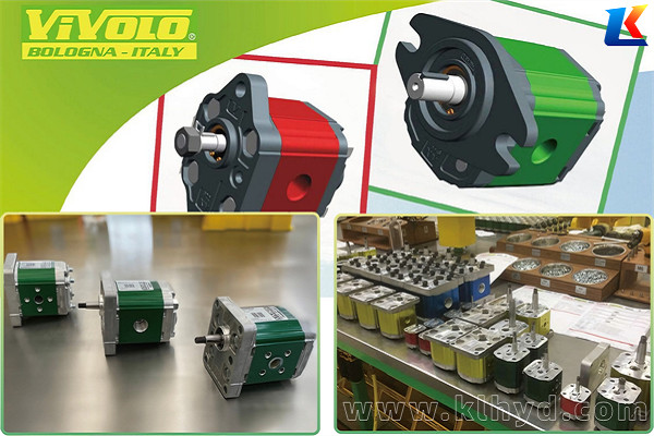
The VIVOIL X3P83 and X3P85 are high-pressure unidirectional hydraulic gear pumps belonging to the XV-3P (Group 3) series, designed and manufactured by VIVOIL (Italy), a professional hydraulic gear pump manufacturer. These pumps adopt an aluminum alloy external gear structure, with cast iron flanges for high-pressure versions, featuring high efficiency, low noise, and long service life. They are widely used in heavy machinery, high-pressure hydraulic systems, and industrial hydraulic stations, providing stable and reliable power output for various hydraulic applications.
This manual provides detailed information on the technical parameters, installation, operation, maintenance, and troubleshooting of the X3P83 and X3P85 hydraulic pumps. Please read this manual carefully before installation and use to ensure safe and correct operation, and to maximize the service life of the pump.
2. Technical Specifications
2.1 General Parameters
|
Parameter
|
X3P83
|
X3P85
|
Unit
|
|---|---|---|---|
|
Series
|
XV-3P (Group 3)
|
XV-3P (Group 3)
|
–
|
|
Pump Type
|
Unidirectional Hydraulic Gear Pump
|
Unidirectional Hydraulic Gear Pump
|
–
|
|
Displacement
|
61
|
64
|
cm³/rev
|
|
Maximum Working Pressure
|
300-320
|
300-320
|
bar
|
|
Maximum Speed
|
3000
|
3000
|
rpm
|
|
Flange Size
|
ø50.8 (Standard)
|
ø50.8 (Standard)
|
–
|
|
Rotation Direction
|
Left (X3P8301) / Right (X3P8302)
|
Left (X3P8501) / Right (X3P8502)
|
–
|
|
Material
|
Aluminum Alloy (High-pressure version with cast iron flange)
|
Aluminum Alloy (High-pressure version with cast iron flange)
|
–
|
|
Operating Temperature Range
|
-20 ~ +80
|
-20 ~ +80
|
℃
|
2.2 Model Description
The model codes of X3P83 and X3P85 follow VIVOIL’s standard naming rules, taking X3P8301ACCA as an example:
-
X3P: Series identifier (XV-3P Group 3 hydraulic gear pump)
-
83: Displacement code (corresponding to 61 cm³/rev)
-
01: Rotation direction (01 = Left rotation; 02 = Right rotation)
-
ACCA: Configuration code (flange type, seal type, etc.)
For detailed configuration information of specific models, please refer to VIVOIL’s official catalog (XP 301.pdf, XP 302.pdf).
3. Installation
3.1 Installation Preparation
-
Check the pump model and specifications to ensure they match the design requirements of the hydraulic system. Confirm the rotation direction, flange type, and connection size of the pump.
-
Prepare necessary installation tools (such as wrenches, screwdrivers) and auxiliary materials (such as sealant, cleaning agent) to ensure the installation process is smooth.
-
Clean the installation surface of the pump and the connecting parts of the hydraulic system to remove dirt, rust, and other impurities, avoiding damage to the pump’s internal components during operation.
-
Check the pump for damage (such as cracks, oil leakage) during transportation. If any damage is found, stop installation and contact VIVOIL’s after-sales service immediately.
3.2 Installation Steps
-
Fix the pump to the installation bracket or the power unit’s mounting surface using bolts. Ensure the installation is firm, and the pump is level (the deviation of the pump shaft from the horizontal direction shall not exceed 0.1 mm/m) to avoid vibration during operation.
-
Connect the pump shaft to the power source (such as a motor) using a coupling. The coaxiality of the pump shaft and the motor shaft shall be within 0.1 mm. Avoid excessive axial or radial force on the pump shaft, which may cause bearing damage.
-
Connect the oil inlet and outlet pipelines of the pump to the hydraulic system. Ensure the pipeline connection is tight, and the oil inlet pipeline is unobstructed to avoid oil suction resistance. The oil outlet pipeline should be equipped with a pressure relief valve to protect the pump from overpressure damage.
-
Apply an appropriate amount of sealant to the flange connection and thread connection to prevent oil leakage. Do not use excessive sealant to avoid blocking the oil circuit.
-
After installation, manually rotate the pump shaft for 2-3 turns to check if it rotates flexibly without jamming or abnormal noise. If any abnormality is found, disassemble and check immediately.
4. Operation
4.1 Pre-Operation Check
-
Check the oil level of the hydraulic oil tank to ensure the oil level is within the specified range (between the upper and lower scale lines of the oil level gauge). The hydraulic oil should be clean and free of impurities.
-
Check the oil quality: Use hydraulic oil that meets the requirements (recommended viscosity: 15-46 cSt at 40℃). Avoid mixing different types of hydraulic oil, which may cause chemical reactions and damage the pump.
-
Check all pipeline connections for looseness or oil leakage. Tighten any loose connections in time.
-
Check the pressure relief valve, filter, and other accessories to ensure they are in normal working condition.
4.2 Start-Up Operation
-
Start the power source (motor) and run it at low speed (1000-1500 rpm) for 2-3 minutes to allow the hydraulic oil to circulate and lubricate all parts of the pump.
-
During the low-speed operation, check the pump for abnormal noise, vibration, or oil leakage. If any abnormality is found, stop the machine immediately and troubleshoot.
-
Gradually increase the speed to the rated speed, and adjust the pressure relief valve to the working pressure required by the system. Ensure the pressure is stable and does not exceed the maximum working pressure of the pump.
-
After the pump runs stably for 5-10 minutes, check the temperature of the pump body (the normal operating temperature should not exceed 80℃). If the temperature is too high, stop the machine and check the oil circuit or cooling system.
4.3 Normal Operation
-
During operation, regularly monitor the working pressure, speed, and temperature of the pump. Ensure all parameters are within the specified range.
-
Avoid long-term operation at the maximum pressure and maximum speed to reduce wear and extend the service life of the pump.
-
Do not suddenly change the working pressure or speed, which may cause impact on the pump and hydraulic system.
-
If the pump needs to be stopped for a long time (more than 1 hour), turn off the power source and release the pressure in the system.
5. Maintenance
5.1 Routine Maintenance
-
Daily maintenance: Check the oil level, oil leakage, and abnormal noise of the pump before and after operation. Clean the surface of the pump and the oil tank to keep it clean.
-
Weekly maintenance: Check the tightness of pipeline connections and bolts. Clean the oil filter to ensure unobstructed oil suction. Check the condition of the hydraulic oil (color, viscosity, etc.). If the oil is turbid or deteriorated, replace it in time.
-
Monthly maintenance: Disassemble and clean the pump’s suction filter and return filter. Check the wear of the pump’s seals. If the seals are aged or damaged, replace them with new ones of the same model.
5.2 Regular Overhaul
The pump should be overhauled regularly (recommended every 6-12 months, depending on the working environment and operating time). The overhaul steps are as follows:
-
Stop the machine, cut off the power source, and release the pressure in the hydraulic system.
-
Disconnect the oil inlet and outlet pipelines and the coupling, and remove the pump from the installation bracket.
-
Disassemble the pump according to the disassembly diagram (refer to VIVOIL’s official technical drawings), and check the internal components (gears, bearings, bushings, seals) for wear, damage, or deformation.
-
Replace worn or damaged components with new ones of the same model. Clean all parts with cleaning agent and dry them thoroughly.
-
Reassemble the pump in the reverse order of disassembly. Ensure the assembly is correct, and the clearance between components meets the technical requirements.
-
Install the pump back to the original position, connect the pipelines and coupling, and perform a test run according to the start-up operation requirements.
5.3 Hydraulic Oil Replacement
-
Replace the hydraulic oil every 6 months or 2000 working hours (whichever comes first). If the working environment is harsh (with more impurities, high temperature), shorten the replacement cycle.
-
When replacing the oil, drain all the old oil from the oil tank, and clean the oil tank and oil filter with cleaning agent.
-
Add new hydraulic oil that meets the requirements to the specified oil level. Run the pump at low speed for 1-2 minutes to allow the new oil to circulate in the system.
6. Troubleshooting
|
Fault Phenomenon
|
Possible Causes
|
Troubleshooting Methods
|
|---|---|---|
|
No oil output or insufficient oil output
|
1. Low oil level in the oil tank; 2. Blocked oil inlet pipeline or filter; 3. Leakage in the oil inlet pipeline; 4. Wear of internal gears or bushings; 5. Incorrect rotation direction
|
1. Add hydraulic oil to the specified level; 2. Clean the pipeline and filter; 3. Tighten the pipeline connections to eliminate leakage; 4. Replace worn gears or bushings; 5. Adjust the rotation direction of the power source
|
|
Excessive pump noise
|
1. Air mixed in the hydraulic system; 2. Insufficient oil suction; 3. Bearing damage; 4. Gear wear or jamming; 5. Pipeline vibration
|
1. Bleed the air in the system; 2. Check the oil inlet pipeline and filter, ensure unobstructed oil suction; 3. Replace the bearing; 4. Replace worn gears or remove jamming; 5. Fix the pipeline to reduce vibration
|
|
Oil leakage
|
1. Loose flange or thread connection; 2. Aged or damaged seals; 3. Cracked pump body; 4. Excessive oil pressure
|
1. Tighten the connections; 2. Replace the seals; 3. Replace the pump body; 4. Adjust the pressure relief valve to reduce the oil pressure
|
|
Excessively high pump temperature
|
1. Poor heat dissipation of the system; 2. Contaminated or deteriorated hydraulic oil; 3. Excessive working pressure or speed; 4. Wear of internal components, increased friction
|
1. Check the cooling system, ensure normal operation; 2. Replace the hydraulic oil; 3. Adjust the pressure and speed to the specified range; 4. Replace worn components
|
|
Unstable working pressure
|
1. Malfunction of the pressure relief valve; 2. Leakage in the system; 3. Blocked oil outlet pipeline; 4. Uneven speed of the power source
|
1. Overhaul or replace the pressure relief valve; 2. Eliminate system leakage; 3. Clean the oil outlet pipeline; 4. Adjust the power source speed to be stable
|
7. Safety Precautions
-
Before installation and operation, read this manual carefully and strictly follow the operating procedures. Unauthorized operation may cause equipment damage or personal injury.
-
During operation, do not touch the rotating parts (such as the coupling) to avoid mechanical injury. Do not open the oil tank or pipeline when the system is under pressure to avoid oil spray and burns.
-
When overhauling or replacing components, cut off the power source and release the system pressure first to ensure safe operation.
-
Use only original VIVOIL spare parts for replacement. Using non-original parts may affect the performance and service life of the pump, and may cause safety hazards.
-
Keep the working environment clean and tidy, avoid hydraulic oil pollution. Dispose of waste hydraulic oil in accordance with relevant environmental protection regulations.


