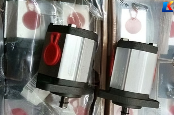
Marzocchi gear pump ALP2A-D-22-FG detailed parameters
1. Model Nomenclature Explanation
-
ALP: Product series, indicating the standard pressure external gear pump, which is widely used in medium and low pressure industrial hydraulic systems due to its stable performance and compact structure.
-
2A: Size group, representing the specific structural size category of the pump, which determines the basic installation dimensions and maximum displacement range of the pump.
-
D: Installation method, standing for flange mounting, which is a common installation form suitable for most industrial equipment installation scenarios”.
-
22: Displacement code, corresponding to the theoretical displacement of the pump (detailed parameters are shown in the following table).
-
FG: Special options, where “F” means equipped with a pressure limiting valve, and “G” means mechanical seal, which can effectively ensure the sealing performance of the pump and prevent oil leakage under working pressure.
2. Core Technical Parameters
|
Parameter Name
|
Specification/Value
|
Unit
|
Description
|
|---|---|---|---|
|
Theoretical Displacement
|
16.0
|
cm³/rev
|
The volume of oil delivered per revolution of the pump shaft under theoretical conditions, which is the core parameter determining the flow rate.
|
|
Maximum Continuous Working Pressure
|
210
|
bar
|
The maximum pressure that the pump can bear continuously during long-term stable operation without damageituen .
|
|
Maximum Intermittent Pressure
|
225
|
bar
|
The maximum pressure that the pump can bear for a short time (intermittent operation) without affecting its service life.
|
|
Peak Pressure
|
240
|
bar
|
The instantaneous maximum pressure that the pump can withstand in extreme working conditions, which cannot be maintained for a long time.
|
|
Maximum Speed
|
2800
|
rpm
|
The maximum rotational speed of the pump shaft allowed during operation; exceeding this speed will cause excessive wear and reduce service life.
|
|
Working Speed Range
|
500 – 2800
|
rpm
|
The optimal rotational speed range for the pump to operate stably, ensuring efficient oil delivery and low noise.
|
|
Flow Rate at 1500 rpm
|
24.0
|
L/min
|
The actual oil delivery flow rate when the pump shaft rotates at 1500 rpm, which is an important reference for matching the hydraulic system.
|
|
Rotation Direction
|
Clockwise (Right-handed)
|
–
|
Standard rotation direction of the pump shaft, which can be customized according to special needs (subject to factory confirmation).
|
|
Pump Body Material
|
Aluminum Alloy
|
–
|
Lightweight, corrosion-resistant, and suitable for medium and low pressure working environments, reducing the overall weight of the equipment.
|
|
Sealing Type
|
Mechanical Seal (G)
|
–
|
Good sealing performance, strong wear resistance, and suitable for long-term high-pressure operation to prevent oil leakage.
|
|
Pressure Protection
|
Equipped with Pressure Limiting Valve (F)
|
–
|
Automatically relieve pressure when the system pressure exceeds the set value, protecting the pump and the entire hydraulic system from damage.
|
3. Structural and Installation Parameters
-
Shaft End Specification: Cone 1:8, with tongue 3.15, terminated with M12x1.25 nut; optional parallel keyed or spline shaft end (subject to model configuration).
-
Installation Center Distance: 36.5 mm, ensuring accurate installation and alignment with the driving device.
-
Mounting Bolt Spacing: 96 x 71.5 mm, standard flange mounting hole spacing, compatible with most standard mounting brackets.
-
Suction/Pressure Port Connection: Flange 40 mm; standard thread specifications include M6 (effective depth 13 mm) and M8 (effective depth 17 mm) for auxiliary connections.
-
Weight: Approximately 5.0 kg, lightweight design facilitates installation and equipment layout.
4. Standard Accessories and Configuration
-
Disc tongue (Part No.: 522057)
-
M12x1.5 bolt (Part No.: 523016)
-
Split elastic rosette (Part No.: 523005)
-
Mechanical seal assembly (matching the “G” option)
-
Pressure limiting valve (matching the “F” option)
5. Application and Working Conditions
-
Application Fields: Suitable for various industrial mechanical hydraulic systems, including machine tools, agricultural machinery, construction machinery, and other equipment that requires stable medium and low pressure oil supply.
-
Working Medium: Hydraulic oil conforming to industrial standards; recommended viscosity range: 10 – 400 cSt.
-
Working Temperature Range: -20°C to +80°C; avoid working in extreme high or low temperature environments for a long time to prevent damage to seals and pump components.
6. Notes
-
The parameters are for reference only; the specific parameters shall be subject to the official product manual or the actual delivered product.
-
During installation, ensure the pump is correctly aligned with the driving device to avoid shaft misalignment, which may cause bearing wear and oil leakage.
-
Regularly check the oil quality and replace the hydraulic oil according to the working conditions to extend the service life of the pump.
-
Do not exceed the maximum pressure and speed limits during operation to prevent irreversible damage to the pump.
| ALP1A-D-1.4-FG
ALP1A-D-2-FG ALP1A-D-4-FG ALP1A-D-6-FG ALP1A-D-8-FG ALP1A-D-10-FG ALP1A-D-12-FG ALP1A-D-13.8-FG ALP1A-S-4-FG ALP1A-S-6-FG ALP1A-S-10-FG ALP1A-F-8-EP ALP1A-D-5-FG |
ALP2A-D-25-FG
ALP2A-D-30-FG ALP2A-D-34-FG ALP2A-D-35.2-FG ALP2A-S-6-FG ALP2A-S-10-FG ALP2A-S-16-FG ALP2A-S-25-FG ALP2-D-6-FG ALP2-D-9-FG ALP2-D-10-FG ALP2-D-12-FG ALP2-D-13-FG |
ALP2-EP-D-20
ALP2-MU-D-25 ALP2BK1-D-16 ALP2BK2-D-20 ALP3A-D-20-FG ALP3A-D-25-FG ALP3A-D-30-FG ALP3A-D-35-FG ALP3A-D-40-FG ALP3A-D-50-FG ALP3A-D-60-FG ALP3A-D-70-FG ALP3A-D-80-FG |
ALP3A-D-87-FG
ALP3A-S-30-FG ALP3A-S-50-FG ALP3-FG-KA-D-40 ALP3-MU-D-50 ALP3A-FA-KA-D-60 ALP3A-MU-D-70 ALP3-D-25-FG ALP3-D-45-FG ALP3A-D-32-EP ALP3A-S-65-EP ALP4A-D-87-FG ALP4A-D-100-FG |
ALP4A-D-120-FG
ALP4A-D-140-FG ALP4A-D-160-FG ALP4A-D-180-FG ALP4A-D-200-FG ALP4A-S-100-FG ALP4A-S-120-FG ALP4E-D-150-FG ALP4A-D-90-EP ALP4A-D-110-FG ALP4A-S-140-EP ALP4A-D-170-FG ALP4-MU-D-190-FG |


