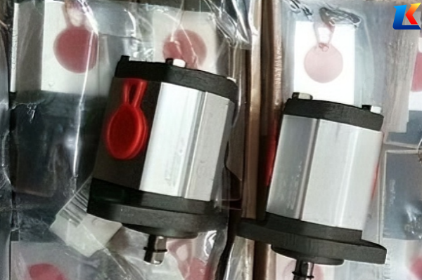
Marzocchi pumps GHP1A-D-8-FG,ALP2A-D-25-FG
General Introduction
Marzocchi produces high-performance external gear pumps covering standard-pressure (ALP series) and high-pressure (GHP series) lines. This manual specifies technical parameters, structural features, installation, operation and maintenance for GHP1A-D-8-FG (high-pressure) and ALP2A-D-25-FG (standard-pressure). All specifications comply with Marzocchi official standards to ensure safe, stable and efficient operation across industrial and mobile hydraulic applications.
1. Model Nomenclature Explanation
1.1 GHP1A-D-8-FG Model Nomenclature
-
GHP: High-pressure external gear pump series, designed for continuous high-pressure operation (up to 250 bar), superior pressure resistance vs. ALP series.
-
1A: Size group (GHP1), displacement range 1–10 cm³/rev, compact dimensions for small-flow systems.
-
D: Flange mounting, rigid installation with minimal vibration.
-
8: Displacement code (theoretical displacement = 7.8 cm³/rev).
-
FG: Special options – F = integrated pressure relief valve (overload protection); G = mechanical seal (high-pressure, leak-proof).
1.2 ALP2A-D-25-FG Model Nomenclature
-
ALP: Standard-pressure external gear pump series, aluminum alloy body, cost-effective for medium-pressure systems.
-
2A: Size group (ALP2), displacement range 9–34 cm³/rev, balanced flow-pressure performance.
-
D: Flange mounting, European standard 4-hole interface.
-
25: Displacement code (theoretical displacement = 17.9 cm³/rev).
-
FG: Special options – F = pressure relief valve; G = mechanical seal (long service life, -10°C to +80°C).
2. Basic Information
|
Item
|
ALP2A-D-25-FG
|
|
|
Brand
|
Marzocchi (Italy)
|
Marzocchi (Italy)
|
|
Type
|
External gear pump (high-pressure)
|
External gear pump (standard-pressure)
|
|
Series
|
GHP1A (high-pressure, aluminum)
|
ALP2A (standard-pressure, aluminum)
|
|
Net Weight
|
Approx. 3.0–3.2 kg
|
Approx. 2.9–3.1 kg
|
|
Structure
|
Single-stage, compact, flange-integrated
|
Single-stage, lightweight, symmetric ports
|
|
Mounting
|
Flange (D)
|
Flange (D)
|
|
Seal
|
Mechanical (G)
|
Mechanical (G)
|
|
Protection
|
Pressure relief valve (F)
|
Pressure relief valve (F)
|
3. Key Technical Specifications
|
Parameter
|
GHP1A-D-8-FG
|
ALP2A-D-25-FG
|
Unit
|
|
Theoretical Displacement
|
7.8
|
17.9
|
cm³/rev
|
|
Max Continuous Pressure
|
250
|
210
|
bar
|
|
Max Intermittent Pressure
|
280
|
225
|
bar
|
|
Peak Pressure
|
300
|
240
|
bar
|
|
Max Speed
|
3600
|
3600
|
rpm
|
|
Min Speed
|
500
|
500
|
rpm
|
|
Flow @1500 rpm
|
11.4–11.7
|
25.5–26.0
|
L/min
|
|
Volumetric Efficiency
|
93
|
92
|
%
|
|
Inlet Pressure
|
0.5–2.5
|
0.8–3.0
|
bar
|
|
Operating Temp
|
-10 to +80
|
-10 to +80
|
°C
|
|
Oil Viscosity (recommended)
|
15–100
|
15–100
|
cSt
|
|
Rotation
|
CCW (CW optional)
|
CCW (CW optional)
|
—
|
4. Material & Construction
GHP1A-D-8-FG
-
Body/Covers: High-strength aluminum alloy, reinforced flanges for high-pressure rigidity.
-
Gears: Case-hardened steel, precision-ground, minimal backlash, low leakage.
-
Bearings: Bronze bushings with pressure-compensation, high load capacity.
-
Seals: Mechanical seal (G) + NBR gaskets, leak-proof under 250 bar continuous.
ALP2A-D-25-FG
-
Body/Covers: Lightweight aluminum alloy, die-cast, good thermal dissipation.
-
Gears: Hardened alloy steel, optimized tooth profile, low noise.
-
Bearings: Self-lubricating bushings, long service life at standard pressure.
-
Seals: Mechanical seal (G) + FKM washers, reliable across temperature ranges.
5. Shaft & Mounting Dimensions
GHP1A-D-8-FG
-
Shaft: Taper 1:8, key 4×4 mm, thread M12×1.25.
-
Shaft Ø: 18 mm; shaft length: 40 mm; pilot Ø: 45 mm.
-
Mounting: 4-hole flange, bolt circle Ø90 mm, M6 bolts.
-
Max torque: 160 Nm; tightening torque: 60±5 Nm.
ALP2A-D-25-FG
-
Shaft: Taper 1:8, key 5×5 mm, thread M12×1.25.
-
Shaft Ø: 20 mm; shaft length: 42 mm; pilot Ø: 50 mm.
-
Mounting: 4-hole flange, bolt circle Ø96 mm, M8 bolts.
-
Max torque: 320 Nm; tightening torque: 70±5 Nm.
6. Port Specifications
|
Port
|
GHP1A-D-8-FG
|
ALP2A-D-25-FG
|
|
Inlet (Suction)
|
1/2″ BSP (GAS)
|
3/4″ BSP (GAS)
|
|
Outlet (Pressure)
|
3/8″ BSP (GAS)
|
1/2″ BSP (GAS)
|
|
Valve Port
|
1/4″ BSP (relief valve)
|
1/4″ BSP (relief valve)
|
7. Product Features
Common Features
-
High Efficiency: Precision gear sets, low internal leakage, consistent output.
-
Low Noise: Optimized gear meshing, rigid body, reduced pulsation.
-
Overload Protection: Integrated pressure relief valve (F) prevents system damage.
-
Long Life: Quality materials, robust bearings, mechanical seal (G).
-
Easy Maintenance: Standardized parts, simple service, compact layout.
GHP1A-D-8-FG Unique
-
High Pressure Rating: 250 bar continuous, ideal for compact high-pressure circuits.
-
Small Flow Precision: Stable low-flow output for precision controls.
-
Compact Footprint: Fits narrow installation spaces.
ALP2A-D-25-FG Unique
-
Balanced Performance: 210 bar / 26 L/min, cost-effective for general industry.
-
Lightweight: Aluminum construction, easy handling.
-
Wide Compatibility: Matches standard industrial hydraulic systems.
8. Application Fields
GHP1A-D-8-FG
-
Precision hydraulic systems (test benches, small actuators)
-
Mobile equipment (small lifts, agricultural attachments)
-
Industrial machinery (packaging, clamping units)
-
High-pressure auxiliary circuits
ALP2A-D-25-FG
-
Industrial hydraulic power units
-
Machine tools (presses, conveyors)
-
Construction machinery (small excavators, loaders)
-
Material handling, lift systems
-
General factory automation
9. Installation Instructions
General Requirements
-
Mount on rigid base; align motor-pump shaft (coaxiality ≤0.1 mm) to avoid vibration.
-
Suction line: tight seals, diameter ≥ pump inlet, length ≤1.5 m, height ≤500 mm.
-
Use clean, filtered hydraulic oil (ISO 4406 cleanliness class 18/15 or better).
-
Prime pump before first start: fill inlet chamber with oil to prevent dry running.
GHP1A-D-8-FG (Flange Mounting)
-
Secure flange with 4×M6 bolts, torque 60±5 Nm.
-
Connect suction/pressure lines; use bonded seals to prevent leaks.
-
Rotate shaft manually to confirm smooth rotation.
ALP2A-D-25-FG (Flange Mounting)
-
Secure flange with 4×M8 bolts, torque 70±5 Nm.
-
Ensure proper alignment; use flexible coupling if misalignment exists.
-
Check all connections for tightness before startup.
10. Operation Instructions
-
Before startup: check oil level, vent air from system, open all valves.
-
Idle run: operate 2–3 minutes at low pressure (<50 bar); check noise, leaks, temperature.
-
Gradually increase pressure to working level; confirm relief valve functions correctly.
-
Operating limits: do not exceed max pressure/speed; monitor housing temp (<80°C).
-
Shutdown: reduce load to zero, stop motor, close isolation valves.
11. Maintenance & Troubleshooting
Routine Maintenance
-
Oil change: Every 2000 operating hours; replace filter element.
-
Seal check: Every 1000 hours; replace mechanical seal if leaking.
-
Bolt torque: Re-tighten mounting/port bolts every 500 hours.
-
Inspection: Check gear/bearing wear every 3000 hours.
Common Faults & Solutions
|
Symptom
|
Possible Causes
|
Remedies
|
|
No/low flow
|
Low oil level; suction leak; gear wear
|
Fill oil; fix suction leaks; replace gears
|
|
Pressure instability
|
Relief valve fault; internal leakage
|
Repair valve; overhaul pump
|
|
Excessive noise
|
Air ingestion; misalignment; cavitation
|
Bleed air; realign; check suction
|
|
Oil leakage
|
Worn seals; loose joints; cracked body
|
Replace seals; tighten joints; replace body
|
12. Notes
-
Parameters apply to standard configurations; custom specs may vary.
-
Do not operate outside rated pressure/speed limits.
-
Use recommended oil viscosity; avoid contaminated/old fluid.
-
Disconnect power and relieve pressure before maintenance.
-
Store in dry, cool place; seal ports to prevent contamination.
-
Contact Marzocchi service for unresolved issues.
13. Warranty Information
Marzocchi provides a 12-month warranty from purchase. Coverage includes defects in materials/workmanship under proper use, installation and maintenance. Warranty excludes damage from misuse, improper installation, lack of maintenance or non-genuine parts. Claim requires proof of purchase and serial number.


