JIHOSTROJ Gear Pump Product Specification
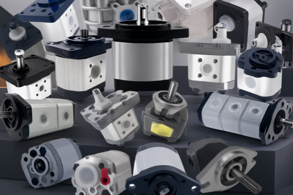
JIHOSTROJ Gear Pump Product Specification
> Version: General English Version (applicable for X / P23 / J / T3 / Q2 / QHD / GHD series, compiled from original manufacturer datasheet, available for technical filing, equipment supporting and maintenance guidance)
> Manufacturer: JIHOSTROJ a.s., Velešín, Czech Republic
> Note: This specification provides general requirements. For specific dimensions, performance curves and bolt torque values, refer to the datasheet of the corresponding series.
Table of Contents
1. Product Overview
2. Model Nomenclature
3. Main Technical Specifications
4. Structure and Working Principle
5. Product Features
6. Application Scope
7. Installation Requirements
8. Commissioning and Trial Operation Procedures
9. Maintenance Regulations
—
1. Product Overview
JIHOSTROJ high-pressure external meshing gear pump adopts an axial floating side plate pressure compensation structure, with fixed displacement. Hydraulic oil is delivered through gear meshing. It inherits aerospace hydraulic component manufacturing technology and features high machining accuracy and excellent volumetric efficiency.
Single, double and triple combined pumps are available, with unidirectional rotation and bidirectional reversible versions optional. Housings are available in lightweight aluminium alloy and heavy-duty grey cast iron. Flanges, shaft extensions, oil ports and seals are modular and optional, compatible with SAE, BSP and metric standards. They are widely used in industrial hydraulics, mobile construction machinery, agricultural machinery and aerospace ground support hydraulic equipment.
2. Model Nomenclature (Taking the mainstream P23 series as an example; other series follow similar logic)
Example: P23-4.4L-S01C02-SG03G03-N
– P23: Series code
– 4.4: Nominal displacement, cm³/rev
– L: Rotation direction (viewed from drive end: L = counter-clockwise; R = clockwise)
– S01: Flange type (S = SAE flange; R = rectangular flange)
– C02: Shaft extension type (parallel key, taper shaft, spline shaft)
– SG03G03: Inlet / pressure port specification
– N: Seal material: N = NBR nitrile rubber; V = FKM fluorocarbon rubber
> Double pump example: P23-4.4/3.3R-R02C03-SM05M05/N
Meaning: Double pump, primary displacement 4.4 cm³/rev, secondary displacement 3.3 cm³/rev, clockwise rotation, NBR seal.
> Reversible version: Equipped with separate drain port. Drain line must return directly to the tank, no back pressure or throttling is allowed.
3. Main Technical Specifications
| Series | Displacement cm³/rev | Continuous Pressure | Peak Pressure | Speed Range |
|---|---|---|---|---|
| X (Micro) | 0.18~3.2 | 230 bar | 260 bar | 800~8000 rpm |
| P23 (Industrial High Pressure) | 0.8~11.8 | 280~300 bar | 300~320 bar | 500~5000 rpm |
| J Series | 2~18 | 280 bar | 300 bar | 500~4000 rpm |
| T3 Series | 4~31 | 240~290 bar | 300~310 bar | 500~4000 rpm |
| Q2 Series | 10~100 | 250 bar | 290 bar | 350~3200 rpm |
| QHD/GHD Heavy-duty | 7~100+ | 250~300 bar | 320~340 bar | 300~3200 rpm |
General Basic Parameters
1. Working fluid: ISO VG32 / VG46 / VG68 anti-wear mineral hydraulic oil; FKM fluorocarbon seal must be selected for phosphate ester and synthetic ester media.
2. Recommended viscosity: 10~100 mm²/s; instantaneous viscosity limit for cold start: 1200 mm²/s
3. Working oil temperature:
– NBR (standard): -20℃ ~ +80℃
– FKM fluorocarbon rubber: -20℃ ~ +120℃
4. Inlet pressure: -0.3 bar ~ +0.5 bar. Severe negative pressure that causes cavitation is prohibited.
5. Oil cleanliness: Recommended NAS Class 8 (ISO4406: 18/15); NAS Class 7 for precision circuits.
6. Pipeline flow velocity: Suction line ≤3 m/s; pressure line ≤8 m/s
4. Structure and Working Principle
Main Components
Housing, driving gear, driven gear (carburized and quenched alloy steel), floating compensation side plate (bronze / composite wear-resistant plate, core component), sliding bearing, shaft seal, O-ring seal. Reversible models are fitted with an external drain port.
Working Principle
With gear rotating and meshing, the volume of the suction chamber increases to form negative pressure for oil intake. Oil is carried by gear tooth spaces to the pressure chamber, where meshing reduces the volume and builds hydraulic pressure. High-pressure oil is introduced to the back of the floating side plate, pressing the plate against the gear end face to automatically compensate axial wear clearance and maintain high volumetric efficiency.
5. Product Features
1. ✅ Axial pressure-compensated side plate: Low internal leakage under high pressure, slow flow attenuation and longer service life compared with ordinary non-compensated gear pumps.
2. ✅ Optimized 12-tooth low-pulsation tooth profile, low vibration and low noise.
3. ✅ Modular design: Customizable flange, shaft extension, oil port, rotation direction and seal; multi-section pump available.
4. ✅ Two housing options: lightweight aluminium alloy and impact-resistant cast iron for heavy loads.
5. ✅ Good self-priming performance, stable pressure build-up at low speed, suitable for mobile equipment driven by diesel engines.
6. ✅ Aerospace-grade machining standard, strict tolerance control, good resistance to pressure shock.
7. ❌ Limitation: Fixed displacement; not suitable for long-time operation under relief pressure. Oil contamination and air ingestion are the main causes of failure.
6. Application Scope
1. Industrial Hydraulics: Hydraulic power units, machine tool clamping and lubrication circuits, injection moulding machines, die-casting machines, automated production lines, auxiliary metallurgical hydraulics.
2. Agricultural Machinery: Tractors, combine harvesters, silage harvesters, balers, seeder hydraulic systems (mainly J and Q2 series).
3. Construction Machinery / Mobile Vehicles: Mini excavators, forklifts, aerial work platforms, sanitation vehicles, wreckers, cranes; QHD/GHD for heavy-duty mining and road construction conditions.
4. Aerospace Ground Support & Special Equipment: Airport ground hydraulic units, fire trucks, forestry machinery, special vehicle hydraulic power sources.
5. Pilot & Lubrication System: X micro series used as pilot pump and lubrication pump.
7. Installation Requirements
1. Drive Connection: Elastic coupling must be used. Belt or chain drive is forbidden. No radial or axial load is allowed on the pump shaft; radial coaxiality deviation ≤0.1 mm.
2. Mounting Position: Horizontal installation is preferred. For reversible pumps, arrange the drain port downward. The drain pipeline returns independently to the tank without throttling or back pressure.
3. Pipeline Layout: Suction line shall be short, straight and large-bore with as few elbows as possible. All joints shall be reliably sealed to prevent air ingress.
4. Cleanliness Control: Do not remove port plugs before installation. Pipelines shall be pickled and flushed. Connect the pump only after system flushing is completed.
5. Rotation Check: Motor rotation direction must match the arrow mark on the pump housing. Reverse rotation will easily damage shaft seal and side plates.
8. Commissioning and Trial Operation Procedures
1. Fill the pump cavity fully with hydraulic oil and bleed air before initial startup. Dry running is strictly forbidden!
2. Fully open the system relief valve to unload pressure.
3. Jog the motor repeatedly to discharge air from pipelines.
4. Run at no load for at least 2 minutes continuously. Check for abnormal noise, leakage and abnormal temperature rise.
5. Increase pressure gradually in stages; direct full-pressure loading in one step is prohibited.
6. The first 50 hours of operation are the running-in period for new pumps. Long-time operation at peak pressure is not recommended.
7. Monitor oil temperature, pressure, vibration and noise during trial run. Formal production can start only after stable operation is confirmed.
9. Maintenance Regulations
> This pump is lubricated by hydraulic oil; no separate grease lubrication point.
1. Daily Inspection (per shift): Check external leakage, abnormal noise and vibration, oil temperature, pressure, tank oil level and air ingress on suction line.
2. 50 h (New pump running-in): Replace hydraulic oil and filter elements.
3. 500 h: Clean suction strainer, replace return filter elements; recheck pump bolt torque and coupling coaxiality.
4. 2000 h: Replace hydraulic oil and all filter elements; inspect shaft seal and O-rings preventively. Disassemble and inspect if flow attenuation exceeds 15%.
5. 5000 h / Annual Overhaul: Disassemble and clean; inspect wear of gears, side plates and bearings. Use original repair kit (side plates + full set of seals) for overhaul.
6. Long-term shutdown (>1 month): Fill pump with anti-rust hydraulic oil, seal ports and store in dry and dust-free environment. Fill oil and bleed air before restarting.