Berarma hydraulic pump 02-PSPK-3-100- FHRM manual
1. Product Overview
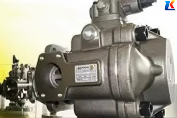
The Berarma 02-PSPK-3-100-FHRM is a medium-high pressure variable displacement vane pump, belonging to the PSPK series of Berarma hydraulic products. It is equipped with a high-precision mechanical pressure compensator and optimized vane structure, featuring high pressure resistance, stable flow output, low energy consumption, and strong adaptability. This pump is mainly applicable to medium-high pressure, large-flow hydraulic systems such as heavy-duty machinery, large hydraulic stations, engineering machinery, and industrial hydraulic equipment, providing reliable and efficient hydraulic power for the stable operation of equipment. The model coding follows Berarma’s standard rules, where “02” represents the size class, “PSPK” denotes the product series, “3-100” indicates the displacement specification, “F” stands for flange mounting, “H” is the high-pressure seal grade, “R” means right rotation (clockwise when viewed from the shaft end), and “M” represents the improved shaft seal type.
2. Technical Parameters
2.1 Basic Information
-
Brand: Berarma
-
Product Type: Variable Displacement Vane Pump
-
Model: 02-PSPK-3-100-FHRM
-
Series: PSPK Series
-
Application: Medium-high pressure hydraulic systems, heavy-duty machinery, large hydraulic stations, engineering machinery, industrial hydraulic equipment
2.2 Key Performance Parameters
-
Geometric Displacement: 100 cm³/rev (according to ISO 3662)
-
Actual Displacement: Approximately 103 cm³/rev (varies by ±3% due to manufacturing tolerances)
-
Maximum Working Pressure: 200 bar (continuous working pressure shall not exceed 80% of the maximum pressure to ensure long service life)
-
Speed Range: 800 – 2000 rpm; Recommended Rated Speed: 1450 rpm
-
Maximum Flow Rate: 149.3 L/min (at 1450 rpm)
-
Pressure Setting Range: 30 – 200 bar (manual pressure control as standard, high-precision mechanical pressure compensator)
-
Noise Level: 65 – 75 dB(A) (at rated speed and pressure)
2.3 Structural & Dimensional Parameters
-
Size Class: Size 3
-
Mounting Flange: ISO 3019-2 (UNI ISO 3019/2) 160B5 HW 4-hole flange
-
Shaft Type: 38 mm diameter, improved shaft seal (Type M), high-strength alloy steel material
-
Rotation Direction: Right (clockwise) when viewed from the shaft end (Type R)
-
Screw Threads: BSP (UNI ISO 228/1) standard
-
Seal Kit: NBR (Nitrile Rubber) + PTFE composite seal, high-pressure seal grade (Type H), oil leakage resistance
-
Inlet Port: G2 (ø 50 mm)
-
Outlet Port: G1.5 (ø 40 mm)
-
Drain Port: G3/8 (maximum allowed drain port pressure: 1.5 bar; must be connected to the oil tank separately, not to the return line manifold)
-
Weight: Approximately 12 kg (single pump, standard control)
2.4 Hydraulic Fluid Requirements
-
Recommended Fluid: HM (ISO 6743-4), HLP (DIN 51524-2), HEES (ISO 15380); 32# or 46# anti-wear hydraulic oil is preferred for medium-high pressure working conditions
-
Viscosity Range: 22 – 90 cSt (mm²/s) at operating temperature; maximum starting viscosity under full flow conditions: 500 cSt
-
Viscosity Index: Minimum 100 (ISO 2909)
-
Fluid Temperature Range: 15 – 65°C (inlet oil temperature ≤55°C, maximum ≤75°C; avoid long-term operation at high temperature to prevent seal aging)
-
Fluid Contamination Level: Maximum acceptable level 19/17/14 (ISO 4406) / Class 8 (NAS 1638); recommended level for longer service life 18/16/13 (ISO 4406) / Class 7 (NAS 1638) to reduce internal component wear
-
Inlet Pressure: 1.0 – 2.0 bar (absolute); avoid insufficient suction pressure to prevent vane damage and cavitation
3. Installation Instructions
3.1 Installation Preparation
-
Confirm the system parameters: Record the working pressure, flow demand, and speed of the hydraulic system to ensure they match the pump’s technical parameters, especially the maximum working pressure shall not exceed 200 bar.
-
Check the pump appearance: Inspect the pump body for damage, cracks, or oil leakage; check whether the connecting parts, pressure regulating device, and seal are intact and free of looseness.
-
Prepare tools and accessories: Prepare hexagon wrench set, torque wrench (range 0-100 N·m), seal installation tool, coupling, and matching high-pressure seals (O-rings, skeleton oil seals, composite seals).
-
Clean the installation area: Ensure the mounting surface, pipeline interface, and connecting parts are clean and free of dirt, debris, or rust to avoid contaminating the hydraulic system and causing internal component wear.
3.2 Installation Steps
-
Fix the pump: Align the pump’s mounting flange with the base, install the mounting bolts symmetrically, and tighten them evenly according to the specified torque (45-50 N·m) to ensure the mounting surface is flat and free of deviation, which avoids uneven stress on the pump body.
-
Connect the pipeline: Connect the inlet and outlet pipelines according to the marked direction (inlet port for oil suction, outlet port for oil discharge); use high-pressure pipelines that match the port size, and ensure the pipeline connection is tight and reliable to avoid oil leakage under high pressure. The inlet pipeline diameter shall not be smaller than the pump’s inlet specification, and the length shall not exceed 2m to reduce suction resistance; the outlet pipeline shall be equipped with a pressure relief valve to protect the pump.
-
Connect the drive shaft: Connect the pump’s drive shaft to the motor shaft using a flexible coupling, ensuring the coaxiality is ≤0.05mm; avoid direct radial or axial loads on the drive shaft. Do not knock the shaft end to prevent internal component damage, and ensure the coupling is installed tightly without looseness.
-
Connect the drain pipeline: Connect the drain port to the oil tank separately, ensure the pipeline is unobstructed and the diameter is not smaller than G3/8; do not connect it to the return line manifold to avoid excessive drain pressure, which may cause shaft seal leakage.
-
Install filters: Install a 10μm precision suction filter at the inlet to protect the pump body from contamination; install a 5μm return filter in the system to maintain oil cleanliness, and configure a pressure gauge at the outlet to monitor the working pressure in real time.
3.3 Post-Installation Inspection
-
Manually turn the pump shaft: Rotate the pump shaft by hand for 2-3 turns to ensure it rotates flexibly without jamming, abnormal noise, or resistance; if there is resistance, check the installation coaxiality and internal components.
-
Check pipeline tightness: Check all pipeline connections, flange connections, and seal positions for looseness or oil leakage; re-tighten if necessary, especially the high-pressure pipeline connections.
-
Check oil level and oil quality: Ensure the oil tank is filled with hydraulic oil that meets the requirements, and the oil level is within the specified range; check the oil quality to avoid using contaminated or expired oil, and exhaust the air in the pipeline before starting.
4. Operation Guidelines
4.1 Start-Up Operation
-
Before starting the motor, confirm that all electrical and hydraulic connections are correct, the pressure regulating valve is set to the minimum pressure (30 bar), and the air in the pipeline has been exhausted.
-
Start the motor in a no-load state, run it at low speed (800-1000 rpm) for 5-8 minutes, and check for abnormal phenomena such as oil leakage, abnormal noise, or overheating of the pump body (normal surface temperature ≤40°C during no-load operation).
-
Gradually increase the speed to the rated speed (1450 rpm), and adjust the pressure regulating valve to the working pressure required by the system; ensure the pressure and flow are stable, and the pressure fluctuation range shall not exceed ±5 bar.
-
After the pump runs stably for 10-15 minutes, check the oil temperature (normal temperature ≤65°C) and all connecting parts again for oil leakage; if any abnormality is found, stop the machine for inspection immediately.
4.2 Normal Operation
-
During operation, regularly monitor the pump’s working pressure, flow, oil temperature, and noise; if any abnormal conditions (such as pressure sudden drop, flow instability, abnormal noise, or overheating) are found, stop the machine for inspection immediately.
-
Do not exceed the maximum working pressure (200 bar) and speed (2000 rpm) of the pump for a long time to avoid accelerating component wear and reducing service life; the continuous working pressure is recommended to be 160 bar or below.
-
Ensure the hydraulic oil is clean and the oil level is sufficient; add oil in a timely manner if the oil level is too low, and check the oil quality regularly; replace the oil and filter element according to the maintenance cycle.
-
Avoid sudden start-up, stop, or pressure shock, which may cause damage to the pump’s internal components (vanes, stator, distribution plate) and seals; when adjusting the pressure, adjust it gradually.
4.3 Shutdown Operation
-
First, reduce the system pressure to the minimum (30 bar) by adjusting the pressure regulating valve, and keep the motor running at low speed for 2-3 minutes to cool the pump body.
-
Stop the motor, and wait for the pump to stop rotating completely and the system pressure to drop to 0 bar.
-
Cut off the power supply of the hydraulic system to ensure safe operation during maintenance.
-
If the pump is not used for a long time, drain the hydraulic oil in the pump and pipeline, clean the pump body and pipelines, apply anti-rust oil to the shaft end and internal components, and store it in a dry, ventilated, and dust-free environment.
5. Maintenance Procedures
5.1 Daily Maintenance
-
Check the oil level and oil quality daily before starting the machine; if the oil is turbid, emulsified, or contains impurities, replace it immediately and clean the oil tank and filter.
-
Inspect the pump body, pipeline connections, and seal positions for oil leakage; replace the seal in a timely manner if leakage is found, especially the high-pressure composite seal.
-
Listen to the pump’s operating noise; if there is abnormal noise (such as sharp friction sound, knocking sound, or whistling sound), stop the machine for inspection.
-
Clean the surface of the pump and the surrounding area to avoid dust and debris accumulation, and check the pressure gauge and filter for normal operation.
5.2 Regular Maintenance
-
Every 300 hours of operation: Replace the hydraulic oil and filter element; clean the oil tank and pipeline, and check the tightness of all connecting bolts.
-
Every 600 hours of operation: Disassemble the pump, inspect the wear of internal components (vanes, stator, rotor, distribution plate), and replace worn components if necessary; check the seal kit and replace it if it is aged or damaged, and clean the pressure compensator.
-
Every 1200 hours of operation: Conduct a comprehensive inspection of the pump, including the drive shaft, bearing, pressure compensator, and coupling; adjust the pressure compensator to ensure its sensitivity and accuracy, and check the coaxiality of the pump and motor.
5.3 Component Replacement Notes
-
When replacing components, use Berarma original accessories to ensure compatibility and performance consistency, especially the vane, stator, and high-pressure seal.
-
Before disassembly, release the system pressure and drain the hydraulic oil to avoid oil splashing and personal injury; wear protective equipment (gloves, goggles) during operation.
-
During disassembly and assembly, use special tools to avoid damaging the pump body and internal components; keep the operation environment clean to prevent impurities from entering the pump.
-
After replacing components, reassemble the pump in the reverse order of disassembly, and conduct a no-load test (5-8 minutes) to ensure the pump operates normally without leakage or abnormal noise.
6. Troubleshooting
|
Abnormal Phenomenon
|
Possible Causes
|
Solutions
|
|---|---|---|
|
Insufficient working pressure
|
1. The pressure compensator setting value is too low; 2. Vanes are stuck or worn; 3. Distribution plate is worn; 4. Oil leakage in the high-pressure pipeline; 5. Pressure relief valve failure
|
1. Re-adjust the pressure compensator to the specified pressure; 2. Clean the vane assembly or replace worn vanes; 3. Check the distribution plate and replace it if necessary; 4. Tighten the pipeline connections or replace the seal; 5. Inspect and repair the pressure relief valve
|
|
Abnormal noise increase
|
1. Air leakage at the suction end or cavitation; 2. Misalignment between the pump and motor; 3. Hydraulic oil contamination or insufficient oil level; 4. Bearing wear or damage; 5. Internal component friction
|
1. Check the suction pipeline and seal to eliminate air leakage, and ensure sufficient inlet pressure; 2. Re-align the pump and motor to ensure coaxiality; 3. Replace the hydraulic oil and filter element, and add oil to the specified level; 4. Replace the bearing; 5. Disassemble the pump to check internal components and eliminate friction
|
|
Unstable flow
|
1. The flow regulator is not set correctly; 2. Excessive gap between vanes and stator; 3. Insufficient suction pressure or cavitation; 4. Oil viscosity is too high or too low; 5. Pressure compensator is insensitive
|
1. Re-calibrate the flow regulating screw; 2. Check the wear of vanes and stator and replace them if necessary; 3. Adjust the suction pressure to the specified range and eliminate cavitation; 4. Replace the hydraulic oil that meets the viscosity requirements; 5. Clean or adjust the pressure compensator
|
|
Oil leakage at the shaft end
|
1. Shaft seal is aged or damaged; 2. The drive shaft is worn; 3. Excessive drain pressure; 4. Improper installation of the shaft seal
|
1. Replace the shaft seal with original accessories; 2. Repair or replace the drive shaft; 3. Check the drain pipeline to ensure it is unobstructed and the pressure is within the specified range; 4. Reinstall the shaft seal correctly
|
|
Pump body overheating
|
1. High oil temperature (exceeding 75°C); 2. Insufficient lubrication or oil quality deterioration; 3. Internal component friction; 4. Excessive working pressure; 5. Poor heat dissipation of the system
|
1. Check the cooling system to reduce oil temperature; 2. Add or replace hydraulic oil; 3. Disassemble the pump to check internal components and eliminate friction; 4. Adjust the working pressure to the specified range; 5. Clean the cooling system and improve heat dissipation
|
7. Safety Precautions
-
Only trained and qualified personnel are allowed to install, operate, and maintain the pump. Before operation, read this manual carefully to understand the safety requirements and operation procedures.
-
During installation and maintenance, must cut off the power supply and release the system pressure to avoid personal injury caused by accidental start-up or oil pressure shock.
-
Do not touch the pump body, pipeline, or other high-temperature components during operation to avoid scalding; the surface temperature of the pump body may exceed 60°C during long-term operation.
-
The hydraulic oil used must meet the specified requirements; do not mix different types or grades of hydraulic oil to avoid reducing the performance of the pump and system, and causing seal damage.
-
When adjusting the pressure and flow, follow the system requirements and do not exceed the maximum limit of the pump to avoid equipment damage and safety accidents; use a pressure gauge to monitor the pressure during adjustment.
-
If the pump fails, stop the machine immediately for inspection; do not force operation to avoid expanding the fault range and causing more serious damage.
-
When storing and transporting the pump, avoid collision, extrusion, and moisture; store it in a dry, ventilated, and non-corrosive environment, and avoid direct sunlight.
8. Replacement Tips
The Berarma PVS series vane pump can directly replace the PSPK series, including the 02-PSPK-3-100-FHRM model. The replacement model is 02-PVS3-100, which has the same installation dimensions, interface standards, and control methods as the PSPK series, while the maximum working pressure is increased to 250 bar, with better pressure resistance, stability, and energy-saving performance. When replacing, follow the replacement steps and key points in the relevant guidelines to ensure the compatibility and stable operation of the system.
9. After-Sales Service
For technical support, maintenance guidance, or accessory purchase, please contact Berarma authorized service center or the local distributor. Provide the pump model (02-PSPK-3-100-FHRM) and fault description to obtain professional and timely services. The product has a standard quality guarantee period of 12 months from the date of purchase; please refer to the product label for specific details.


